This TECH page covers much more then just replacingthe injectors. When the injectors are being replaced for performancereasons (or just need to be replaced), there are a lot of other thingsthat can be easily handled with the plenum off the engine. Injectorreplacement, PCV valve replacement, valve cover seal replacement,throttle body water jacket bypass, safety boost cut solenoid removal,plenum exchange, throttle body replacement and a little bit of paintingare all covered on this page. I used Mike H's page from www.TTAZ.org and JaimeZX's page that was based on Mike's page as references to put together this page.
This is on a 91 TT, the NA is similar enough to follow this document.It should be obvious when something is not applicable to the NA.
Parts:
All links for parts go to CourtesyParts.com for on-line parts ordering.
There are two different styles of injectors for the 90-96Z.There is the pintle style (old) and the pintle-less style (new). Eachhas a different set of O-rings and insulators. The old style has asquare electrical connector with a metal clip, the new style has anovalish electrical connector with a built in plastic squeeze clip.
Old style injector
New style injector
For an injector replacement procedure with old style injectors: 14033-30P02 - plenum to lower intake gasket 16635-10V02 - upper injector insulator (6 req'd) 16635-10V10 - lower injector insulator (6 req'd) 16618-10V00 - lower injector O-ring (6 req'd) 16618-53J00 - lower injector O-ring (6 req'd) 16618-10V05 - upper injector O-ring (6 req'd) A6440-N7685 - 5" bulk high pressure fuel hose (to connect the fuel rails) 14719-30P05 - EGR gasket (2 req'd) Old style injector replacement kit
For an injector replacement procedure with new style injectors: 14033-30P03 - plenum to lower intake gasket 16635-53J00 - upper injector insulator (6 req'd) 16635-88G00 - lower injector insulator (6 req'd) 16618-53J00 - lower injector O-ring (6 req'd) 16618-10V05 - upper injector O-ring (6 req'd) A6440-N7685 - 5" bulk high pressure fuel hose (to connect the fuel rails) 14719-30P05 - EGR gasket (2 req'd) New style injector replacement kit
If ordering stock injectors, also note the Z shipped with 'blue'or 'black' dotted injectors. All that is available from Nissan now isthe 'black' dotted injector, who's part numbers have superceded boththe 'blue' and 'black' dotted injectors over time. The differencebetween the two had to do with the spray pattern of the injector. Iwould *highly* recommend replacing all six injectors even if only one'needs' replacing. Once one goes, the others have to work harder tomake up for the lost output. Keep in mind all three cylinders in a bankfeed a single O2 sensor... so when the ECU detects a lean conditionbecause one injector in the bank is failing, it pours in more fuel tomake up for it, so the engine really isn't running at an optimum selftuneable level. Generally when one injector fails, the others follow inshort order.
16600-15V02 - NA old style injector 6 or 1 pieces 16600-10Y01 - NA new style injector 6 or 1 pieces 16600-40P07 - TT old style injector 6 or 1 pieces 16600-21U00 - TT new style injector 6 or 1 pieces
Optional: 11810-40P00 - PCV valves (2 req'd) 11823-30P01 - PCV hose 11823-30P11 - PCV hose 11826-30P10 - PCV hose (rear) 11823-40P01 - PCV hose (TT passenger front valve cover) 11823-40P11 - PCV hose (TT driver front valve cover) 11823-30P20 - PCV hose (NA passenger front valve cover) 11823-30P12 - PCV hose (NA driver front valve cover) All 5 NA PCV hoses and 2 valves All 5 TT PCV hoses and 2 valves 23785-40F00 - IAAC Gasket 14099-30P01 - Hose from IAAC to air regulator 14099-30P02 - Hose from air regulator to balance tube 14033-30P05 - Large balance tube O-ring (2 req'd) 14033-30P06 - Small balance tube O-ring (1 req'd) 22675-10Y00 - fuel pressure damper 22670-10Y00 - fuel pressure regulator 16440-30P01 - long fuel lines from filter and to fuel return (2 req'd) A6440-N7685- 22" total bulk high pressure fuel line for all fuel lines on top ofthe engine (includes 5" fuel rail connection listed in the top kit) 16400-Q0805 - fuel filter 24079-25P26 - harnesses with new injector connectors (2 req'd) 6' of 8mm (5/16") heater/fuel hose for TB bypass 3' of 6mm (1/4") vacuum hose for TB bypass 1' of 5mm (3/16") vacuum hose for TB bypass 6mm (1/4") hose barb (barrel) for TB bypass 5mm (3/16") hose barb (barrel) for TB bypass M5 x 16 mm with .80mm pitch hex head socket screws (12 req'd)
Special Tools:
10mm stubby wrench
Procedure:
Removing the plenum
1. Relieve fuel pressure.Disconnect the negative terminal of the battery. Jack up the car. Iprefer to lift the car up to me then have to bend over the whole time.There's a couple places a stepping stool might be required to reach themiddle of the engine, but it's easier to bend over half as far 95% ofthe time and have to use a step in places then bending over 100% of thetime.
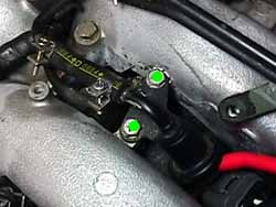
2. Remove center trim cover (4 x 5mm Hex head bolts) (green dot in 1.).
1.
3. Disconnect throttle cables by loosening the front nuts on the bracket (2 x 14mm nuts) (yellow dot in 2.),then swing the cables out of the throttle body control rod cable waysin the front of the engine. The cables are held in place in threelocations along the way to the plenum. Remove all the holding tabs (3 x10mm bolts). Remove the cruise control solenoid from the fender well (2x 10 mm bolts). Swing the main throttle cable out of the way.
2.
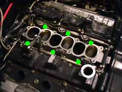
4. Disconnect all the hoses to the balance tube on the back of the engine (5 for TTs, 4 for NAs) (yellow dots in 3. & 4.).Disconnect the wiring bracket on the passenger side of the plenum (1 x10 mm). Remove the balance tube (3 x 12 mm acorn nuts, 2 x 12 mm bolts)(green dots in 3.&4.). Be careful not to drop the O-rings that seal the balance tube to the plenum into the plenum (5. & 6.). Stuff all three holes with rags to keep debris from getting in there (7.). Remove the wiring bracket from the plenum.
3.
4.
5.
6.
7.
5. Remove all upper fuel rail pieces. Refer to the fuel filter replacementpage to see how to relieve fuel pressure. Spray all hose fittings withPB Blaster penetrating lubricant. This is the best product I have everused for this purpose. Disconnect the small vacuum lines on the driverside (yellow dots in 8.). Disconnect the fuel lines from the upper fuel rail on the plenum (2 x phillips hose clamps) (green dots in 8.).Remove all the bolts holding the fuel pressure regulator, fuel pressuredamper, and upper rail itself from the engine (6 x 10 mm bolts) (greendots in 9. & 10.). Loosen the whichever clamps aremost convenient which are holding the pressure regulator and damper tothe lower fuel rail (under the plenum). Remove the upper fuel rail,regulator and damper (most of 10.).
8.
9.
10.
6. Remove the coil packs by disconnecting the plugs to each one (yellow dots in 11.). The wires might be trapped by keepers. Remove the keepers (blue dot in 11.) and the oil cap (red dot in 11.) to get the wires pulled back. Remove the bolts holding the coil packs in place (12 x 12 mm bolts) (green dots in 11.).Remove the coil packs my pulling them straight out at the angle theyare installed at. They have a clip to hold them on the spark plug topsand might require a bit of pressure to get them to come out (12.).I recommend keeping them in the order they are removed. Put the oil capback in place to keep debris from getting in the engine.
11.
12.
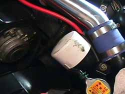
7. Remove the 4 intake hoses (8 x 8 mm hose clamps). I have somecaps to go over the exposed intercooler intake piping. They are 2" PVCpipe caps w/ a loop of foam on the inside (13.). They slide right over the ends of the pipes to keep any and all debris and bolts from going into the pipes (14. & 15.). Stillen's intercoolers come with some perfectly sized red caps that can be used the same way.
13.
14.
15.
8. Disconnect the injector connectors (blue dots in 16.) and the fuel rail temp. sensor (green dot in 16.).For the injector connectors, I use a pair of dental picks to pry thewire clips outwards and then carefully pull the connector up. By now,unless it's a low mileage 90-94 or a 95+ the connectors will beextremely brittle. Expect them to break, hopefully it won't ruin theconnector. The injector connectors changed in 95 to a more heatresistant design. For these, simply squeeze the clip and pull them off.
9. Disconnect the grounds on both sides of the rear of the plenum (2 x 10 mm bolts) (white dots in 16.). Disconnect the detonation sensor plug (red dot in 16.), dead center pointing upwards on a bracket on the rear of the plenum. Disconnect the O2 sensor (yellow dot in 16.) and variable valve timing connector (orange dot in 16.)just to the driver side of the detonation sensor connector on brackets.The last three are the worst, they have the injector style connectors(all years). The idle air adjusting unit has two and the idle airregulator has one. They are bolted to the backside of the plenum on thedriver side. Take your time and try not to destroy the connectors onthem. The idle air adjusting unit has a light blue and a yellowconnector on it (blue and yellow dots in 17. respectively). Theblue one is sideways and the yellow one points upwards. The connectoron the idle air adjusting unit is light blue and oriented the same asthe other blue connector, it's further towards the center of the engineon the back of the plenum. Disconnect both throttle position sensorconnectors (green dots in 18.). Disconnect the safety boost cutsolenoid plugs on each side. They are the square black connectorsmidway along the sides of the engine, or still clipped to the hard pipecoming up from each turbo.
10. Remove the idle air tube running the length of the driverside of the plenum. Pull the clamps back at the front on the curvedhose and on the rear where it goes into the idle air adjusting unit onthe back corner of the plenum. The tubing might have the wiring harnessclipped to it. Disconnect the harness and remove the tubing.
11. Disconnect the two small hoses from under the fronts of the throttle bodies.
16.
17.
18.
12. On the driver side, disconnect both hoses coming downward fromthe throttle body area. One goes straight down (yellow dot in 19.), the other comes out at an angle (green dot in 19.). Blaster works great here. Remove the dipstick (blue dot in 20.).Disconnect the two large vacuum lines going to the brake booster andthe clutch booster (TT only) (2 x clamps) (white dots in 20.),flip them back out of the way, or totally remove them (2 x clamps).Disconnect the hose going from the clutch booster vacuum fitting treetowards the front of the car (1 x clamp) (green dot in 20.).Disconnect the small hose that is coupled with the small hose from theupper fuel rail off the brake booster fitting tree (yellow dot in 20.). Remove both fitting trees from the plenum (orange dots in 20.). Pull the clamp back on the PCV valve's hose so it can come off the valve when the plenum comes out.
19.
20.
13. Remove both turbo outlet pipes. Loosen up the hose clamps on thetop of the rubber coupling on the turbo (2 x 8 mm hose clamps). Removethe two bolts holding the pipes onto the plenum (2 x 10 mm) (blue dotin 21.). Remove the entire assemblies. The wastegate solenoidconnectors might be clipped onto the hard pipe part of the assembly. Onthe driver side, there is a bracket coming down from the plenum towarda bracket on another piece of tubing, disconnect it (1 x 10 mm). Itused to have one of the hoses disconnected in the last step attached toit (green dot in 19.). Use a stubby 10mm wrench to disconnect the EGR return tubes on either side of the plenum (green dots in 21.).
21.
14. Remove the side bracket bolts (4 x 12 mm bolts) (orange dots in 19.).Remove the tubing on passenger side of the plenum. Disconnect the EGRfeed tubes from the bottom of the plenum (4 x 10 mm bolts) (green dotsin 19.). A 10 mm stubby wrench will get things started, and a1/4" drive socket on a short extension will get the bolts removedquickly.
15. On the passenger side, disconnect the hose coming from theback corner of the plenum and going down to the turbo (1 x clamp).Disconnect the small EGR vacuum hose on the side of the plenum near thelast hose disconnected. There is a same size hose coming out of theback side of the plenum on the corner, disconnect it. Blaster worksgreat here as well. Pull the clamp back on the PCV valve's hose so itcan come off the valve when the plenum comes out.
16. Remove the plenum from the lower intake by removing the bolts on the top center (8 x 12 mm bolts) (22.). The short bolt is the front passenger side (red dot in 22.), the odd bolt with the threaded hole in the top is second from the rear on the passenger side (orange dot in 22.). Carefully pull the plenum upward and forward. There are still two hoses connected to the rear of the plenum in the middle (23.).Disconnect these and remove the plenum entirely (2 x clamps).Immediately cover the lower intake openings so no debris or bolts endup down in there (24.).
22.
23.
24.
17. Remove the caps on the injectors. I recommend using a manualimpact driver with the correct size phillips bit on it to remove thescrews (12 x phillips screws). If the screw top gets stripped, they areincredibly difficult to remove for no good reason (25. & 26.). Be careful not to loose the rubber insulators (red dot in 26.) and metal shims (yellow dot in 26.) on top of each injector .
25.
26.
18. Remove the bracket on the rear of the lower intake (1 x 10 mm bolt) (27.), it has the ground strap going onto it from the lower fuel rail. Remove the fuel rail with the injectors (6 x 10 mm bolts) (28.), don't loose the small black plastic insulators on the fuel rail.
19. Soak the injector seals with lots of Blaster. Set it aside for now if continuing on with some of the other jobs.
27.
28.
Other tasks:
Removing the valve covers to paint or replace seals. Also covers all the PCV hoses to be replaced
20. Remove the PCV hose from the fitting on the driver sideexhaust valve cover (1 x clamp). Remove the PCV hose coming from therear of the driver side exhaust valve cover (2 x clamp). Remove the PCVhose from the tube on the rear corner of the passenger side of theengine (1 x clamp). Disconnect the PCV breather hoses from the fittingson the front of each intake valve cover (2 x clamps) (29.).
29.
21. Remove the plastic spark plug hole covers (8 x 12 mm bolts) (red dots in 30.).Be careful not to lose the rubber seals at the ends of the tubes.Remove the intake valve covers (16 x phillips screws) (yellow dot in 30.). Cover the cam and valve assemblies to keep debris from getting on them. Removing the exhaust cam covers (blue dot in 30.)(16 x 10 mm bolts) is a little more difficult. On the driver side, thePCV hose on the rear has to be disconnected and be careful with thedipstick bracket. The side brackets holding the plenum to the blockmight have to be removed (4 x 12 mm bolts) to get to the bolt behindthem. The use of a 1/4" drive 10mm socket on a u-joint will help toremove the bolts. Cover those cam assemblies as well once the valvecover is removed.
22. I took the opportunity to paint the intake valve covers onthis car. High temp Duplicolor 1608 red looked good to the owner. Peelout the rubber gasket, remove the rubber screw insulators, use achemical paint stripper (using all cautionary methods: safety glasses,chemical resistant gloves, etc.) to remove the paint from the outside.Use degreaser to clean the inside if necessary. Be careful not to breakthe plastic breather openings on the underside of the cover. Repaintthe covers as desired. The exhaust covers should be about the same.Remove the gaskets (carefully scrape clean the mating surfaces ifrequired, do not scratch any of the mating surfaces, so leaks myresult), clean the covers up and paint them. Clean the screws, boltsand insulators.
30.
23. Put the rear PCV hose back in place with the clamps in themiddle. Note the orientation of the hose as it is 'sloped' to one side.Position it where the small end is angled toward the block. Put thegasket or sealant on the covers and reinstall them (16 x insulators, 16x phillips screws, 16 x 10 mm bolts). I used some Permatex RTV to sealup possible leak points in the covers (31.). The exhaust coversare difficult to get back on without getting sealant all over the placeand potentially compromising the seal. Be careful to put the dipstickbracket on top of the exhaust valve cover flange and not under it.Tighten all four covers in a crisscross pattern. Torque the exhaustvalve cover bolts to 4.6-6.1 ft-lbs. Torque the intake valve coverscrews to 0.7-2.2 ft-lbs. (32.).
24. Reconnect the rear PCV hose and side the clamps back inplace (2 x clamps). Pay attention to the orientation of the clamps,they should 'point' to the rear. Reconnect each of the side PCV hosesDisconnect the PCV breather hoses from the fittings on the front ofeach intake valve cover (2 x clamps), point the clamps outwards.Reconnect the PCV breather hoses on the fronts of the intake valvecovers (2 x clamps). If the tubing was removed to repaint the covers,use a plastic mallet to pound them back into place. Install the plasticspark plug hole covers (8 x 12 mm bolts). Be careful not to lose therubber seals at the ends of the tubes. No torque spec is listed.
31.
32.
Bypassing the throttle body water jackets
25. Use the 1/4" heater hose to bypass the throttle body waterjackets. Attach it to the rear tube on the passenger side and swing itaround the corner to the water pipe coming up off the turbo (33.). Cut it to proper length and clamp it down (2 x clamps). Do the same thing on the driver side (2 x clamps) (34.-36.). Picture 34. shows the second hose not pictured back in 23.. NAs will be configured slightly differently.
33.
34.
35.
36.
Removing the safety boost cut solenoids if an EVC is installed.
26. Remove both safety boost cut solenoids (4 x 8 mm bolts) (37.).Pull them straight up and the hoses will come off the intake tubing.They should already be disconnected from the wastegates if the EVC isinstalled. Cap off the nipples on each intake pipe with 5/32" rubbercaps. Use zip ties to secure the nipples. This part of the intake tractis always under vacuum, never boost (38.) but a boost pressure check would blow them off.
37.
38.
Cleaning up the plenum (or trading for a polished one)
27. Disconnect any hoses going to the throttle bodies (39. & 40.). Remove all the hoses and tubes from the underside of the plenum (4 x 10 mm bolts and a lot of hose clamps) (41.). Remove the idle air adjusting unit (4 x 8 mm long bolts) (42.) and the idle air regulator from the rear of the plenum (2 x 8 mm short bolts) (43.). Remove the throttle bodies and mid linkage (7 x 6 mm hex head bolts) (mid linkage in 44.)from the plenum. Note how the throttle bodies fit to the mid linkage.Remove the plug from the passenger rear corner of the plenum on the top(1 x 14 mm bolt) (45.).
28. Make sure the throttle body and plenum gasket matingsurfaces are clean. If a different plenum is going onto the car, checkevery single hole on it for proper threads, etc. Finding ruined threadson the EGR bolt holes on the bottom of the plenum later is not fun todeal with. If holes need to be tapped out, make sure ALL the metalshavings are out of the plenum. Cleaning the plenum with degreaser andwater is OK, just make sure to dry off the outside so it doesn't getwater spots on it. If using some non-petroleum cleaner, make sure it'saluminum alloy friendly.
29. Attach the mid linkage on the new plenum (3 x 6 mm hex headbolts, the short one goes on the bottom). Torque in 3 steps: fingertight, 3.6 ft-lbs, 14 ft-lbs. Put some grease in the sockets on theends of the linkages. Slip the throttle body linkages into the midlinkage fittings. Attach the throttle bodies to the plenum using freshgaskets (8 x 6 mm hex head bolts). Torque in 2 steps: 6.5-8.0 ft-lbs,13-16 ft-lbs.
30. If the throttle body water jackets are not being bypassed,attach the tubing with new hoses on the underside of the plenum (4 x 10mm bolts and a lot of hose clamps). I won't go into detail, but here for TT or here for NA are all the parts. I'd replace every rubber hose under there. Otherwise this has all been eliminated in step 25 above.
31. The only downside I could find to leaving off all the tubingon the bottom is there are two clips for the driver side O2 sensor andVTC solenoid connectors on it where it goes around the idle airadjusting unit and the idle air regulator. I opted to remove all of it.Not only does it bypass the throttle body water jackets, but it alsobypasses a vacuum hose going to the EGR valve and one going to thecarbon canister in the front of the car.
32. Make sure the idle air adjusting unit gasket mating surfaceis clean. Attach the idle air adjusting unit to the plenum with a newgasket (4 x 8 mm long bolts) and the idle air regulator. Torque all to6.2-8 ft-lbs. Attach the new hose between the idle air adjusting unitand the idle air regulator (2 x hose clamps). Replace the plug from thepassenger rear corner of the plenum on the top (1 x 14 mm bolt). Torqueto 12-14 ft-lbs. Snug in the PCV valves, there should be a little bitof thread exposed even when they are seated. There is no torque speclisted for them (2 x 19 mm valves).
39.
40.
41.
42.
43.
44.
45.
Replacing the injectors
33. If the injectors haven't been soaking in Blaster, soak themnow. It's incredible how easy this is after a Blaster bath. Split therail in half by removing the fuel hose holding the halves together (2 xphillips hose clamps). I made a tool to extract the injectors from therail using an 11mm Craftsman socket to cover the pintle end of theinjector (bottom) and a cut up PVC pipe fitting on the electricalconnector side. Simply put the socket over the pintle and the PVC toolon the top over the injector, but on the mounting ears. Tighten thevice a turn or two and the injector will pop right out of it's swollenseals (46.). Repeat for all 6 injectors.
46.
34. Clean up the rail and prep it for the new injectors. Leave theprotective plastic covers on the pintle ends. Put both new rubber Orings on each injector, using some motor oil to lubricate them. Use a24mm 12pt 1/2" drive Craftsman socket on the fuel rail, and I used acrescent wrench on the connector end (someone tell me what a good PVCfitting tool would be made of here, I didn't have time and had to workwith the tools in the garage.) in the vice to reverse the removaltechnique (47.). If using the longer hex head screws, it mightbe possible to pull the injectors into place by putting the caps withthe upper insulator in place. Start each screw and tighten a little biteach until the cap is tight against the rail. Make sure the O rings goin smoothly and don't get pinched, the top of the injector doesn't getsquashed in and also make sure the connectors are squared up and facingoutward. They can be twisted slightly afterwards, but I wouldn't pushmy luck. If anything doesn't feel right, stop now, back up and fix it.It's heartbreaking to do all this work and then have to backtrack allthe way back in to replace s cheap O ring if it gets pinched (48.).
35. Cut a matching length of high pressure fuel hose toreconnect the rail halves to each other. Loosely clamp them togetherwith the clamp screw heads facing forwards, not up. Remove any of theold injector seals in the lower intake that didn't come out with theinjectors. Carefully clean the seal seats and oil up the new injectorseals, placing them in the lower intake the same way the old ones werein there (they have a bevel and I forgot to note which way they fit).Remove the protective covers on the injector pintles.
47.
48.
36. Use 12 M5 x 16 mm with .80mm pitch hex head socket screws with alock washer and a washer on each of them on the injector caps (49.).Place the small metal half washer on top of each one, followed by therubber insulator, and finally the cap. Note the flat orientation withthe edge of the cap. Torque the hex head screws to 1.8 - 2.4 ft-lbs (50.).Reattach the ground strap and the detonation sensor connector bracketto the back of the lower intake with the tab pointing backwards.Tighten the clamps on the front of the fuel rail. With them pointingforwards, they can be tightened later if they loosen up for any reasonwith out having to tear down the top of the engine to get to them.
37. Gently set the fuel rail back into the seals on the lowerintake. Make certain everything is fitting as it should. Again, apinched seal at this point is a pain to come back and fix afterwards.Take some extra time examining things now to avoid re-doing this part.Make sure the black plastic insulators are on the fuel rail (12 pcs.).Bolt the fuel rail back to the lower intake (6 x 10 mm bolts). Notorque spec is listed in the service manual.
38. If upgrading the injectors to a higher flow rate, don'tforget they need a different ECU chip installed to handle the differentpulse width for correct fuel flow. See the ECU chip swap TECH page.
49.
50.
Installing the plenum
The steps are basically the reverse order, I'll just add notes:
39. If all the hoses were pulled from the underside of theplenum, the EGR hose will need to be extended and joined on thepassenger side. Use the 3/16" hose and barb to extend the hose. Cut toproper length. The carbon canister hose on the driver side that was onthe underside tubing will now need to be extended and joined on thebalance tube when it's reinstalled. Use the 1/4" hose and barb toextend the hose. Cut to proper length.
40. Remove the rags from the lower intake. Set the new plenumto lower intake gasket on the lower intake. The side with the factorysealant goes downward. Set the plenum carefully down on the gasket. Ifthe throttle body water jackets were not bypassed, reconnect the twohoses at the very rear of the plenum first (23. & 34.).Make sure nothing is keeping the plenum from seating properly on thelower intake. It's too easy to get the detonation sensor wire orsomething else trapped in there, causing a huge vacuum leak. Seat theEGR tubes into the bottom of the plenum. If the throttle body hoseswere bypassed, make certain the hose coming from the front driver sideto the rear moves easily under the plenum and isn't pinched anywhere.Pinching this line will kill a turbo in short order.
41. Torque the plenum bolts (8 x 12 mm bolts) to 12 - 15 ft-lbs. in a crisscross pattern.
42. The EGR tube bolts (4 x 10 mm bolts) are torqued to 6.2 to 8 ft - lbs.
43. There is no torque spec listed for the side braces on theplenum, or the fuel rail. Use good judgment and remember this is a softaluminum alloy, it will strip out holes easily. I'd think 6 - 8 ft-lbsis max torque.
44. Replace all fuel hose couplings with new high pressure fuelhose. It's a good time to replace the fuel pressure damper and fuelpressure regulator if the car has some miles on it.
45. The balance tube nuts and bolts (3 x 12 mm acorn nuts, 2 x 12 mm bolts) are torqued to 12 - 15 ft-lbs.
46. I opted to leave the metal wire tree on the passenger sideof the plenum off. I just looped the wires back on themselves and awayfrom the turbos and exhaust. If the underside tubing was removed, theO2 sensor and VTC connectors won't have clips to mount on. They resteasily on the back of the plenum.