| The Z32 came with minimal alignment adjustments.On the front, the only adjustment is the toe-in. Caster and camber cannotbe adjusted without special after market parts. The upper links, commonlycalled A-arms, control the amount of camber. This is the amount the wheelslean inward (negative) or possibly outward (positive). The more negativecamber, the better the car will corner. This comes with the price of moreinner edge wear on the tires, as the inside edge takes more travel abusethen the entire tire will take under cornering. If the car is only forracing, then numbers like -2.0 or -2.5 degrees of camber are acceptable.For most people, it's not. The factory spec is -1.35 to -0.05 degrees *unladen*.Laden alignment number should be -.5 to -1.5 degrees, I think this is thebest way to measure. I think the alignment specs have changed along theway.. like in '92 according to the Hunter bench I get my alignment doneon. I need to verify the real numbers. The alignment specialist will knowthe answers. Adjustable upper links are usually required when the car isolder and proper alignment specs cannot be met, the car has been in a frontend wreck and the frame wasn't straightened properly, or the car has beenlowered or the suspension geometry has been altered somehow to effect camber.There are two basic styles of adjustable upper links: The Stillen 'slideplate' design and the Japanese 'turnbuckle' design. I'll cover installationof both, but all illustrations are of the Japanese "Midori" adjustableupper links. This installation is on a '93 TT. Special thanks to Paul (KC) for the doc this is based on Timing: The best time would be when any other suspension work is being donethat requires an alignment, or when proper alignment requires it. Special Tools:
18" x 1/2" extension
14 and 17 mm 1/2" sockets
1/2" breaker bar
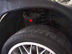
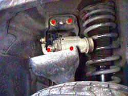
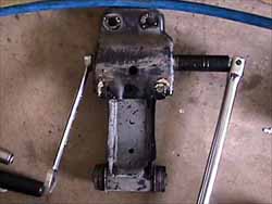
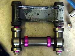
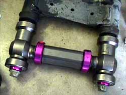
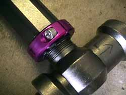
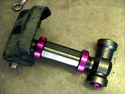
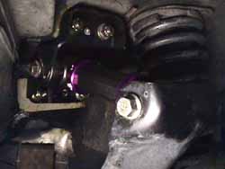
Torque wrench Procedure: 1. Lift the front end of the car high enough to stretch out the frontsuspension (1.) and secure with jack stands on the frame rails.Observe all safety precautions. Read the rest of the page and soak allinvolved bolts and nuts with a penetrating lubricant. I recommend PB Blaster. 2. Remove the bolt connecting the upper link to the third link (reddot in 1.) (1 x 17 mm bolt, 1 x 17 mm nut). The 17 mm nuts holdingthe arm into the bracket and third member, along with the bracket to theframe are all 'one use' nuts. A slightly misleading term, they can be re-used,but they won't self lock again unless they are re-set by striking the topside of them with a metal hammer. I generally don't bother with this, asthe torque specs are high enough to keep things from coming loose on theirown. Cleaning the nuts and bolts, then applying Loc-Tite will do the samething for people wanting to be slightly more cautious. The wheel will saga bit more when the third link comes loose from the upper link. 3. Lift up the upper link a little and remove the two lower nuts holdingthe bracket to the frame (lower red dots in 2.) (2 x 14 mm nuts).The 'bolts' are part of a plate assembly in the engine bay, so there isno bolt head to put a wrench on. Make sure to be fully seated on the nutsbefore trying to remove them, they are easy to round off. A 18" x 1/2"extension covered with a towel or rag to prevent scratching the fenderpaint on a good sized breaker bar make this easier then trying to twista wrench inside the wheel well. Remove the upper nuts holding the bracketto the frame. If these nuts have never been removed before, the self locksare binding the bolt properly. Air tools might have some difficulty withthis, just use the breaker bar to get them started & the air tool tofinish them off. 4. Remove the bracket from the frame. Remove the upper link from thebracket ( 3.) (1 x 17 mm bolt, 1 x 17 mm nut). 5. Use the upper link bolts to check the length of the new adjustableupper links against the factory upper links. This gets the length in theballpark to get the car over to the alignment rack. For the Japanese style links (Midoris): Twist in both ends in until the link isas short as it can get without binding. Keep in mind one end isn't 'rightytighty', but backwards for the link to work properly. Get the link properlysituated, as there is a front and back, and left and right, they shouldbe marked as what side and end each are, at least the Midori's are (red dotstickers go toward the engine, longer side goes forward). Keepingthe same 'alignment' slowly twist the center section until the link extendsto the same length as the factory upper link. Use the bolts to check thelength (4. & 5.). Loosen the locking collars (6.)(2 x 5 mm hex) and twist them around to where they will be accessible oncemounted back in the car. For the Stillen style links: Stillen says their links are symmetricaland work in any
orientation. However this seems to be the only correct working orientation: 1. Angled-in zerk - inside end and facing down
2. Straight-up zerk - outside end and facing up
3. Adjustment bolts - heads are facing up
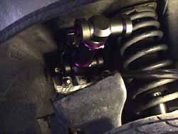
4. Adjustment gear - toward the rear of the car Loosen the locking nuts (4 x 1/2") and run the ends to the appropriatelength using the upper link bolts to check the correct length. Torque thelock nuts to 15 ft-lbs. Thoroughly cover the shafts of the link bolts withhigh temp, non lithium, water resistant chassis/bearing grease. Stillenrecommends against white lithium grease, they also recommend relubing ever10k miles to avoid bushing squeak. 6. Attach adjustable upper link to the bracket using the bolt with the"9B" marking on the head of the bolt (this one is a little thicker thanthe other one which should be marked "9") and a new nut (7.) (1x 17 mm bolt, 1 x 17 mm nut). Torque to 65-80 ft-lbs. 7. Reattach upper link bracket to inner fender well (8.) (2 x17 mm, 2 x 14 mm). Torque the 14 mm to 43-58 ft lbs. Torque the 17 mm nutsto 80-94 ft-lbs. 8. Attach the other end of the upper link to the third link using thebolt marked "9". (9.) (1 x 17 mm bolt, 1 x 17 mm nut). Torque to65-80 ft-lbs. 9. On the Japanese style: Tighten the locking collars to 14-21 ft-lbs(2 x 5 mm hex). On Stillen style: Use the grease fittings to push morewhite lithium grease into the ends of the links to keep them very welllubricated. The Japanese "Midoris" have bearings in the ends and don'tneed grease. 10. Lower the car, get an alignment done ASAP. REV 2-21-02
|