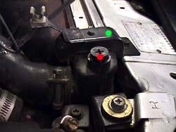
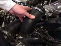
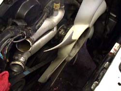
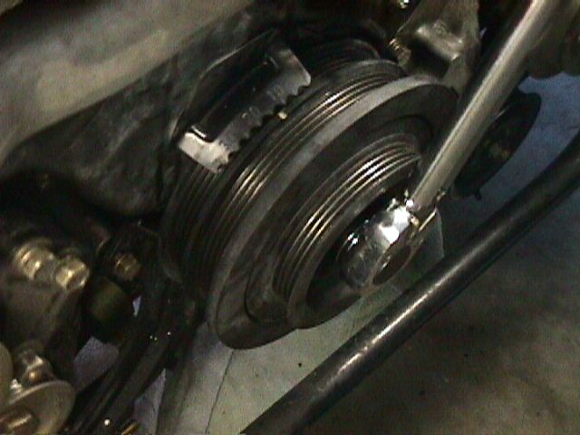
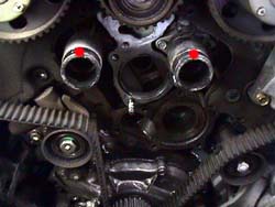
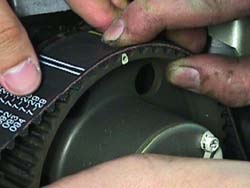
| The largest part of 60k maintenanceis replacing the items on the front of the engine: timing belt, water pump,seals, etc. Not really a hard job, but very time consuming. I made thisguide a little more detailed then most, hoping a few people that normallywouldn't tackle a project like this will dive in with confidence. Thiswas performed on Jeff B's '91 TT 5spd (57k miles!). The '96s are slightlydifferent due to the lack of Variable Valve Timing on the intake cams.Special thanks to Kyle @ SGPfor proofing the page & providing a few new tricks to use. Timing: There has been some discussion about what the maintenance interval shouldbe for changing the timing belt. The earlier Z service manuals recommendevery 60k miles or 48 months. The later ones suggest the NA can go as faras 105k miles before replacing the belt. From what I've learned it wasa misprint, that's actually the distance in km, not miles. The VG30DE(TT)engine is low tolerance. In other words, if the belt slips or is installedimproperly, there is a strong possibility the valves will hit the topsof the pistons. Something expensive to repair, but easily avoided if thismaintenance is completed when it's supposed to be, either based on milesor time. I've had people e-mail me and say 'I had X miles on my timingbelt & it looks just fine', while this is true (I've got 20+ hangingon my wall as trophies, they all look 'OK'), I've had a couple unfortunatepeople mail me & say 'I had X miles on my timing belt & it lookedfine, except the break in the middle'. Please read through this entire procedure before even buying the partsto do it. It's very easy to get stuck in a position of no return. I'vewritten the article where if followed in the order listed, this is minimized.There are a few situations (the crank sprocket) where the proper toolsmake life simple, just be aware of the potential difficulties I list indoing this procedure. There's also some notes for air wrench users to speedthings up. Some of the picture's contents don't match the actual orderof the steps. I've made several revisions to the order since the pics weretaken, etc. Part Numbers: Timing Belt:NA2/89-7/92 13028-16V00
7/92+ 13028-45P00 or 13028-45P86 TT7/89-4/93 13028-16V00
4/93+ 13028-45P00 or 13028-45P86 Auto-TensionerThermostat:9/91-9/93 California Auto TT 21200-42L05
all others 21200-42L00 Water Outlet Hoses (2 req'd):Water Pump:Water Pump Gasket:Alternator Belt:TT A172M-67A0MVW
NA A172M-V530MVW A/C Belt:Power Steering Belt:TT7/89-9/93 A192M-42L0AVW
9/93+ A195M-F650AVW Cam Seals (4 req'd):Main Seal:2/89-9/93 13042-16V00
9/93+ 13042-10Y00 Intake Cam Sprocket O-rings (2 req'd):7/89-9/93 01001-00191
9/93+ 13037-75T00 Intake Cam Sprocket Springs (2 req'd):Main Crank Sprocket (you might have to remove the current one the hardway):Crank Rear Spacer13022-45V00 (Nissan's computers have the wrong part number listed,this is correct) Special thanks to Steve Richardsonof CourtesyNissan for helping me put together the part number list.Special Tools: An assistant (not necessary, but makes things much simpler)
Pulley puller
Seal puller (not necessary)
Thin Lexan Plastic (see step 36)
5 mm hex head socket
6 mm hex head socket
White paint pen
Plastic faced mallet
Pry bar
Air impact wrench and impact sockets (makes certain steps much simpler)
27 mm socket Other items: Permatex Blue silicone gasket maker
2 gallons of distilled (pure, not spring) water
1 gallon of antifreeze
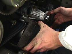
Optional bottle of Redline Water Wetter
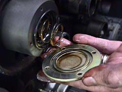
Optional underdrive pulley & smallerbelts
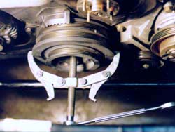
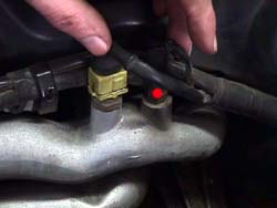
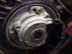
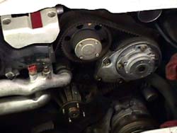
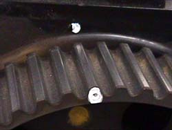
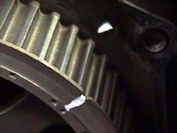
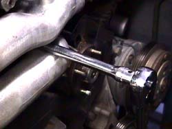
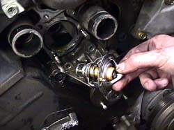
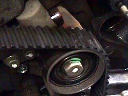
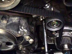
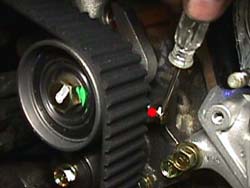
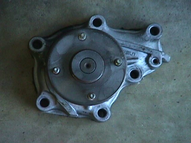
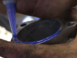
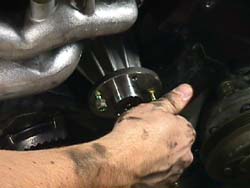
I highly recommend getting a set of Mechanixgloves Procedure: 1. Disconnect the negative terminal on the battery. 2. Raise the front of the car & put it on ramps or jack stands,observe all safety precessions. NOTE: For more detailed instruction on removing the accessory drivebelts and crank pulley, read through the UnderdrivePulley Install page. 3. Remove the lower engine shield (6 x 10 mm) 4. Open radiator petcock & drain fluid into a bucket (be VERY carefulnot to scald yourself if the car is warm). Once fluid is draining out intothe bucket, open the radiator cap and remove the secondary fill plug (reddot in 1.) on the opposite side of the radiator. Let the radiatordrain completely. 5. Remove the lower fan shroud from the upper fan shroud and radiator(3 clips). Remove the lower radiator hose bracket (1 x 10 mm). 6. On turbos, remove the left and right throttle body intake hoses (2.).Put rags into each of the intercooler tubes at the front to keep anythingfrom falling into there (4 hose clamps x 8 mm). 7. Remove the upper radiator brackets (2 x 10 mm) (green dot in 1.). 8. On '93 & earlier Zs, remove the recall power transistor wirewraps (3.) from the upper radiator hoses. 9. Remove the upper radiator hose. (2 hose clamps x 10 mm). Disconnectthe lower radiator hose from the radiator, let it drain into the bucket.Disconnect the lower radiator hose from the engine. Remove the lower radiatorhose. Disconnect the coolant overflow tube from the radiator (1 hose clamp).Check that it's off the radiator shroud down the driver's side. There'sa spot it 'tucks' into to hold it in place about halfway down. Make surethe hose isn't allowed to drain, it will empty the overflow reservoir.I generally loop it around a hose on the driver side to keep it from fallingdown and draining. There are transmission fluid cooler hoses going intothe radiator on the driver side on the automatic transmission models. Disconnectthem where they come up to the lower radiator hose under the engine andlet the contents drain into the bucket. 10. Remove the lower fan shroud (3 x clips). Remove the radiator. Onturbos, the intercooler tubes will be in the way, wiggle the radiator aroundsome to get it clear of them. Don't loose the two round rubber mountinggrommets on the bottom of the radiator (4.). 11. Remove the fan from the fan clutch (4 x 10 mm). Remove fan clutchassembly from the water pump (4 x 10 mm). 12. Loosen the AC idler pulley (1 x 14 mm) and the adjustment bolt (1x 12 mm). 13. Loosen the locking bolt (1 x 12 mm), the adjustment bolt (1 x 12mm) & the pivot bolt (1 x 17 mm) on the alternator. Remove the boltholding the adjustment bracket to the block, pull the bracket away fromthe block (1 x 12 mm). 14. Loosen the locking nut (1 x 12), the adjustment bolt (1 x 12 mm)& the pivot bolt (1 x 14 mm through the pulley's hole) on the powersteering pump. 15. Remove all the accessory drive belts. 16. Unbolt the top & bottom bolt (2 x 8 mm) on the power transistorbracket, removing the entire assembly. Unplug the engine temperature sensor(yellow w/ the wire clip) & the thermal sensor (black spade plug) (reddot in 7.). Unscrew the bracket holding the harness under the crankangle sensor. On '90-'93s Pull back the rubber shield on the crank anglesensor plug (8.) & carefully remove the connector (another wireclip) or on the '94+, just unplug it. Bend the entire front engine wiringharness back out of the way. 17. Remove the plastic upper right timing belt cover (3 x phillips/8mm, 5 x 5 mm hex head) (9.). Try to keep the screws in the appropriateholes. There are a lot of different lengths of bolt and they get easilyconfused if removed. There's one phillips/8 mm in the lower center of bothplastic covers that should be unscrewed last. It's going into a spacerstud behind it and most of the time it backs the stud out instead of leavingthe stud there. 18. Turn the crank clockwise using the crank bolt until the dots onthe exposed sprockets line up with the dots on the back covers (paintedwhite for illustration purposes (10 & 11.).This places theengine's rotation at #1 Top Dead Center (TDC). Don't expect the belt'smarksto line up, only the dots on the sprocket and the back cover. Rotatethe crank about 10 degrees BeforeTDC (BTDC) (counter clockwise). Thismakes installing the belt easier later on. 19a. For 5spds, put the car in 5th gear, make sure the parking brakeis engaged. Loosen the crank pulley bolt (1 x 27 mm) (5.). Makesure to use a real penetrating lubricant beforehand. I recommend Blasterbrand. An air wrench makes this much easier. 19b. For autos, if an air wrench is available, try it first to loosenthe crank bolt (1 x 27 mm). Make sure to use a real penetrating lubricantbeforehand. I recommend Blaster brand. If the air wrench alone doesn'twork, or isn't available, here's the alternate method: NOTE: I don't havepics of this step specifically yet. Use the belt wrapping technique usedlater on the cam sprockets here. Basicallywrap the rear set of grooves on the pulley with the old AC belt and loopthe excess over to the bracket of the alternator (it loops around behindthe adjustment bolt) to hold the pulley still. Doing this WILL ruin thebelt, so make sure it's not going to be re-used. 20. Once the crank bolt is broken loose, loosen it about 1/2" to givethe pulley some room to move forward with the bolt still in the threads.Mount the pulley puller on the crank pulley, using the dimple in the headof the crank bolt as the contact point for the puller's center bolt. Clampthe arms on the THICK part of the pulley, not the very front (6.).The pulley is made of soft iron an will break easily if the front lip isused as the arm's contact points. Remove the crank pulley. Be careful withthe woodruff key exposed on the crankshaft. Also be extremely careful withthe AC condensor (the other radiator looking thing now exposed), it's ratherfragile & a a good dent might cause it to leak out all the freon. Notgood at all. 21. Move the coolant bucket to front center under the engine. Removethe water inlet tube (lower aluminum tube) (2 x 12 mm nuts, 1 X 6 mm hexhead) (12.). Use a screwdriver to remove the thermostat (13.).Be careful not to scratch the mating surfaces. 22. Squeeze the clamps on the water outlet tubes (red dots 14.),push them back onto the rubber hoses. Remove the water outlet tube (3 x6 mm hex head). Remove all 4 clamps, remove both short water hoses. 23. Remove the plastic upper left timing belt cover (2 x phillips/8mm, 5 x 5 mm hex head). Remember the one phillips/8 mm that's going intothespacer stud. Try to keep the screws in the appropriate holes. There area lot of different lengths of bolt and they get easily confused if removed.Remove the metal lower timing belt cover (6 x 8 mm). If the spacer studsdidn't come off with the plastic timing belt covers, remove them now (2x 17 mm bolts) 24. Remove the water pump (6 x 12mm) (15.). Clean off allthe coolant fittings with a putty knife to ensure a good seal when replacingthe parts. Be careful not to scratch the mating surfaces while cleaningoff the old sealer. A small wire brush will quickly remove old sealer withoutdamaging the mating surfaces. 25. Remove the Crank angle sensor mounting bracket ( 3 x 12 mm) andcrank angle sensor (16.). 26. Loosen the exhaust cam sprocket bolts (8 x 11 mm) (17.). 27. Remove the intake cam sprocket front covers (8 x 7 mm) (18.)there is a spring & O-ring behind the cover for the Variable ValveTiming on the '90-'95s, don't drop them. A small amount of oil will leakout from the inside of the sprocket, this is normal. 28. Jeff's auto-tensioner was almost at full extension (20.).Take one of the 10 mm bolts from the fan and screw it into the retentionhole on the tensioner (red dot in 28.). When it's slowlytightened,it will be long enough to remove the tension from the belt. Remove thebelt auto-tensioner (2 x 12 mm bolts, 1 x 12 mm nut). Loosen the nutfirst, then remove the bolt to the left, then the bolt to the right. Removethe timing belt. Use the old belt to wrap around each sprocket tocontrolthem while letting them come to rest. The cams will want to rotate afewdegrees rather violently, try to avoid this because the VG30DE(TT)engineis low tolerance & the valves can make contact with the pistonsunder certain conditions.Always be careful around the cam sprockets when the timing belt is noton themand under tension. The cam lobes will want to relieve spring tensionwheneverpossible. When the sprockets turn, the valves are coming to 'rest' intheir seats. It's actually a good thing most of the time. The passengerside cams will definitely rotate. The drivers sidecams are already settled. NOTE: Here's a simple way I use tohold the intake sprockets in place while removing or tightening the boltsholding them in place. 29. Remove the intake cam sprockets (2 x 19 mm) (20.). The intakecam sprockets changed in '94, the newer ones are silver and beefier looking(FWIW they are also adjustable). The ones shown here are '91. Use the beltwrap technique in the note above to hold them in place. 30. Remove the exhaust cam sprockets (8 x 11 mm) (17.). 31. Remove the upper middle idler pulley (1 x 14 mm). 32. Remove the back metal covers to access the cam seals (8 x 10 mm).There might be a stud on the either side to remove if it didn't come offwith the plastic cover. 33. Remove the seals by carefully bending the outside ring with a punchor screwdriver (21.). DO NOT scratch the camshaft or outer sealingsurface. Just barely dent the seal enough to get a screwdriver over thetop & be able to pry down a little bit to pop it out. I can not stressenough how important it is to NOT scratch any of the mating surfaces. Scratchingthe cam will lead to VERY EXPENSIVE repairs because the seal will leakoil out into the timing belt area. Not something I care to think about.If a seal puller is available, it can be used on the intake cam seals,they don't seal to the camshafts, so the puller can be inserted and used. 34. Carefully clean the cam shaft & head mating surfaces with arag. Lightly oil the new seal with motor oil inside & out. Slip thenew cam seal over the end of the camshaft with the 'solid' side facingoutward. Gently push the seal into place, then use one of the old seals(cleaned) as a spacer to tap the new seal in place using ONLY a plasticface mallet to avoid scratching/damaging the camshaft (22.). 35. Use a pry bar to slide the crank sprocket & washer off the crank(23.). Be careful with the woodruff keys exposed on the crankshaft.If the sprocket doesn't come off, the simplest solution is to just cutit off. This is where the new crank sprocket and rear washer come intoplay. I don't waste time trying to heat it up etc. Striking it with a metalhammer is not a good idea either as the sprocket's metal is very soft andthe teeth on the sprocket will become flat without much effort. With thegear at top dead center, cut through the gear over the key way with a 4"air cut-off wheel. Just slice across it being careful to not nick the crankor cut into the aluminum oil pump assembly behind it (too badly at least).Once a sufficient slot is cut, hammer a chisel into the slot. The sprocketwill eventually crack over the keyway and then it will easily slide off. 36. Remove the front main seal the same way as the cam seals (24.).Replacing the main seal is MUCH more difficult then the cam seals becauseof the shape of the crankshaft itself. There is a step the seal must getover to start to seat. All of the front seals have a tiny tension springinside the seal, this spring doesn't stay seated very well while installingthe seal. There is an easy way to do it with an additional 'tool' and aharder way to do it without. Easy way: Get some thin Lexan plastic, cut a 4.5" x3" rectangle out of it. Oil up the seal insideand out, then roll it up and slip it into the seal. Take this and slipit all over the crank and push it up into the seal's seat. The idea isto use it as a ramp over the step on the crank & into position withoutrolling over the seal and letting the spring in the seal loose. Use anotherold seal and slip it over the plastic and use it as a spacer to tap thenew seal in place. once everything is seated, pull the old seal off theplastic, then gently pull the plastic out of there. If everything is lubedup, it should slip right out, leaving the seal perfectly seated and thespring on the inside remaining on the inside. Genius idea from Jim Gahl!I've used it several times now. Just make sure the seal is going in withthe 'solid' side facing forward like the others. Harder way: I slip the seal up to the step with the 'solid' sidefacing outward & then pushed the bottom part into the seat. The sealis then at about a 45 degree angle with the top leaning out. I them putboth of my thumbs on the bottom center of the seal and worked my thumbsaround the edges keeping tension on the seal to up it upward as the sealstarted to seat, watching to make sure the spring doesn't come out of theseal. The technique is to maintain tension as the seal is worked in place,so the spring stays in place because the back part of the seal is NOT beingallowed to roll over as it makes contact with the step on the crank. Verypoor engineering on Nissan's part for maintenance purposes. All Nissanneeded to do was taper the step off a bit and life would be OK. Be VERYpatient here. After the rear lip of the seal is over the step, use an oldseal to help tap the new on in place, starting from the bottom & finallyworking the way to the top. Seat the crank seal the same way the cam seals were seated. Run a fingerall the way around the seal to make sure it is seated evenly, the bottomof the seal can't be seen without an inspection mirror.37. Install the washer & the crank sprocket over the woodruff keyson the crank shaft. The flat washer goes on the back side of the sprocket.If the lower belt cover loops around the crank, then a second flat washergoes on the front of the sprocket. If the lower belt cover doesn't looparound the crank, the bevel edged washer goes on the front with the bevelfacing the rear to make the belt fall back onto the sprocket if it wereto come forward. 38. Install the metal back covers (8 x 10 mm). 39. Clean off the ends of the intake cams. Install the exhaust cam sprockets(8 x 11 mm). The sprockets are self keying on the metal dowel pins. Justhand tighten the bolts for now. 40. Install the intake cam sprockets (2 x 19 mm), they are self keyingtoo. Use the wrap technique. Torque to 90-98 ft-lbs (for '90-'95, not surehow/what the '96s look like) 41. Install the intake cam sprocket front covers. Make sure the O-ringsare seated in the groove on the back of the cover & the spring is seatedin the middle. Tighten the bolts (8 x 7 mm) to 1.1-1.8 ft-lbs. 42. Install the upper middle idler pulley (1 x 14). Torque to 32-43ft-lbs. 43. The arrow on the new timing belt will point to the front of thecar. There are 5 marks on the outside of the new timing belt. 4 are closetogether, locate these & position them across the tops of the sprocketswith the 4th mark to the passenger side exhaust cam sprocket (25.).This positions the 5th mark on the correct side of the crank sprocket at#1 TDC. 44. Start positioning the belt marks on the appropriate sprocket teethbeginning with the crank sprocket. Stick a screwdriver/pry bar betweenthe belt & the oil pump shielding to hold the belt in place. Pull thebelt and line the marks on the exhaust cam sprocket up on the driver'sside, then the intake cam sprocket next to it & so on (we're 1 toothoff in 26.). If the sprockets are not close to the right area toland the marks on, wrap the old timing belt around the sprocket and rotateit until it's close enough to 'capture' under the mark. The dots on the backmetal covers are for reference only at this point, same with the notch in theoil pump. All 15 indications willnever line up perfectly. The only thing that matters are the lines on thebelt and the marks on the sprockets lining up properly. 45. Install the new auto-tensioner on the stud & get the washers/nutstarted (1 x 12 mm). Have the helper push the auto-tensioner in place witha pry bar against the back of the auto-tensioner and the power steeringpump bracket until the other bolts can be started (2 x 12 mm) The rightone will be first, the left one second. (27.). Torque all to 12-15ft-lbs. 46. Remove the 10 mm retaining bolt on the new auto-tensioner (insideedge, gold color w/ white paint on it) (red dot in 28.) to let theidler pulley arm push against the belt. 47. Shift the transmission to neutral. Put the crank bolt back in (makesure the thick washer is on it) & rotate the crank 2 times (720 degrees)clockwise to ensure the valves will not make contact with the pistons whenthe engine is started. Check the auto-tensioner's extension. It shouldbe at about 4 mm. If it's not, put the retention bolt back in theauto-tensioner to remove tension on the belt. Slowlytighten the retaining bolt to relieve tension. If the retaining bolt istightened too quickly, the casting on the tensioner will break. If itdoes, it's not a deal breaker. Just maintain tension on the belt andpry the backside of it instead of using the retaining bolt to retractthe pulley. Loosen the two bolts andnut on the auto-tensioner, re adjust the position of the tensioner,tightenthe bolts and nut again. Torque all to 12-15 ft-lbs. Release theretentionbolt and go back to the start of this step. Repeat until the tension iscorrect. 48. Torque the exhaust cam sprocket bolts to 10-14 ft-lbs. in a criss-crosspattern. 49. Put Permatex Blue on the mating surface of the water pump (29.)& install or use the gasket (6 x 12 mm, the 'stud' goes in the furthestright hole 13.). Torque to 12-15 ft-lbs. I didn't know the gasketexisted until speaking with Steve Richardsonof CourtesyNissan while getting the part numbers for everything. 50. Install bottom metal cover (6 x 8 mm, the shortest bolt goesin the top hole on the right side) (30.). There's a bracket on thelower right side that's difficult to get around to get the cover in place. 51. Install the plastic upper left timing belt cover (2 x phillips/8mm, 5 x 5 mm hex head, the lower middle is shorter bolt) (31.).If the spacer studs came out with either plastic cover, be aware they needto be the first bolt tightened. If they had to be removed to get the backcovers off, put them back now (2 x 17 mm) and torque to 12-15 ft-lbs. 52. Install the crank angle sensor (3 x 12 mm) and torque to 12-15 ft-lbs.There is a key inside the shaft to align it properly with the cam shaftsplines, make sure everything lines up properly. Install the plastic upperright timing belt cover (3 x phillips/8 mm, 5 x 5 mm hex head). 53. Install the two new short rubber water outlet hoses. Clamp the rubberhoses, making sure the left front one it pointing down & the rightfront one is pointing to the bottom-right. The rears can both face upward(32.). Put Permatex Blue on the mating surface of the water outlettube & install (4 x 6 mm hex head) (33.). Torque to 12-15 ft-lbs.Re-clamp the rubber hoses, making sure the left front one is pointing down& the right front one is pointing to the bottom-right still. 54. Install the new thermostat, making sure the top indication on thethermostat is the top. Put Permatex Blue on the mating surface of the waterinlet tube (34.) & install (2 X 12 mm nuts & 1 X 6 mm hexhead). Torque to 12-14 ft-lbs. 55a. For 5spds, put the transmission into 5th gear. Remove the crankbolt (1 x 27 mm). Install the pulley (optionally the underdrive pulley).Torque to 159-174 ft-lbs. 55b. For autos, remove the crank bolt (1 x 27 mm). Wrap the pulley inreverse fashion as was probably required to loosen the crank bolt. Installthe pulley (optionally the underdrive pulley). Torque to 159-174 ft-lbs. 56. Jam-nut the water pump studs in place (35.): Hand screw inthe stud (short end goes into the pump). Thread on 1 10 mm nut, threadon a second one after it. Use two 10 mm wrenches (or wrench & socket)to tighten the nuts against each other. Tighten the stud into the hub likea bolt until it seats (about 4-6 ft-lbs). Use the two wrenches to breakthe nuts away from each other, making sure the stud stays in place. Removeboth nuts & repeat for the other 3 studs. 57. Bring the front electrical harness across the front of the engine.Plug the crank angle sensor, thermal sensor, temperature sensor back in,bolt the power transistor back to the bracket (2 x 8 mm). 58. Put the water pump pulley on the pump hub. Re-attach the alternatoradjustment bracket (1 x 12 mm). Torque to 16-22 ft-lbs. Install the newdrive belts. The longest goes over the waterpump and alternator, the middlesize goes around the AC compressor. The shortest goes over the power steeringpump. 59. Install the fan and fan clutch (8 x 10 mm). Torque to 4.3-7.2 ft-lbs. 60. Tighten drive belts to appropriate specs, or 1/4" deflection atthe midpoints except the power steering belt which is closer to 1/2" undera 22 lb. load. 61. Torque the AC idler pulley (1 x 14 mm) to 23 ft-lbs. 62. Torque the alternator locking bolt (1 x 12 mm) to 20-25 ft-lbs.Torque the alternator pivot bolt (1 x 17 mm) to 12-15 ft-lbs. 63. Torque the power steering pump locking nut (1 x 12 mm) to 20-25ft-lbs. 64. Install the radiator. Make sure the radiator is seated properlyin the lower mounting grommets. On the automatic models, plug the transmissioncooler lines back in and tighten them (2 hose clamps x 10 mm). 65. Connect the negative cable to the battery (be ready with alarm buttons).Put the transmission in neutral. Make sure the parking brake is on. Startthe engine to check the belt tension (especially if an underdrive pulleywas installed). Don't let the engine run for too long without coolant.Make necessary adjustments. 66. Install the upper radiator brackets (2 x 10 mm). install the lowerradiator shroud (3 x clips). Install the lower radiator hose (2 hose clampsx 10 mm). Install the upper radiator hose (2 hose clamps x 10 mm). Installthe lower radiator hose bracket (1 x 10 mm). Replace the wire wraps onthe power transistor wires. Connect the coolant overflow tube (1 x hoseclamp). 67. On turbos, remove the rags from each intercooler tube & installthe two throttle body intake hoses (4 hose clamps x 8 mm). 68. Fill the radiator with 1/2-2/3 gallon of antifreeze (and optional1/2 bottle of Redline's Water Wetter) & then start filling with distilled(pure, not 'spring' or 'drinking') water. Once the radiator is full, startthe car & let it idle. Turn on the air conditioner. Keep filling theradiator as required. After the temperature gauge reaches operating temperatureplus a couple minutes the radiator should be full. Screw in the secondaryfill plug. Cap the radiator. Check the coolant level in the overflow reservoir. 69. Check for coolant leaks on the radiator & hose clamps. Tightenwhere it leaks if necessary. 70. Install the lower engine shielding (6 x 10 mm). 71. Return the car to the ground. When making the first drive, keepan eye on the temperature gauge. If it starts to overheat, turn on theheater full blast to bring the tenmp down. Wait for the car to cool off& fill the radiator with more water. REV: 11-3-03
|