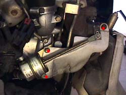
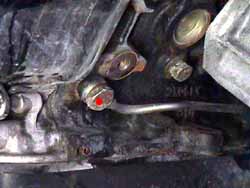
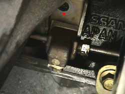
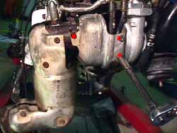
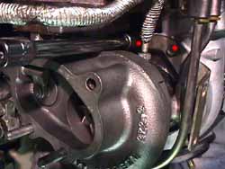
| Moreair flowed through the cylinder equals more potential horsepower. Sincethe turbo Z depends on forced induction to keep up with higher displacementengines, the easiest way to raise the bar is to install larger turbos tomove more air. For a few dollars more then the OEM turbos, a set of Sport500s can be purchased as replacements. Considering the amount of laborinvolved in this, it's pretty senseless not do perform some sort of upgrade.The service manual's turbo removal section indicates the turbos can bereplaced with the engine in the car. While this is true, with the propertools it's much quicker to remove the engine and do the job outside thechassis. This way the newly installed turbos can be torqued to all appropriatespecs, leaving nothing on the installation to question. I personally knowpeople who have done it by the book. I tried & realized the passengerside is hard, the driver's side is seemingly impossible. Save a lot offrustrated hours and pull the engine. It's also a great opportunity todo some other maintenance items. This install is on Shahram's '93 TT. Timing:
When the urge strikes & the pocket book is fat, this is thebest time. Or when the exhaust is smoking and the diagnosis is turboseal failure. Parts:
2 turbos, custom, or OEM PNs 14411, 14411+A
5 Rubber water feed lines, PNs 14056W, 14056WB, 14056WA, 14056WC, 14056WD
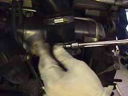
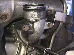
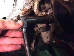
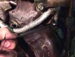
4 Metal water feed lines, PNs 15192P, 15192R, 15192PA, 15192RA
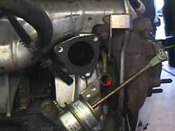
10 Total copper seals, all PN 15188A
1 Copper seal (listed as two PNs) PN 15192G for the passenger oil feed
2 Oil feed lines, PNs 15192+A, I recommend 15192 & 15192+B as a 2 piece line, while 15192 can be a single piece line.
2 Oil return gaskets, PN 15196
2 Oil return rubber hose couplings, PN 15198
2 Intake inlet gaskets, PN ***sec.165? listed*** dunno
2 Intake outlet gaskets, PN 14456M
2 Metal turbo flange gaskets, PN 14415
2 Metal precat gaskets, PN 14445 Special tools:
1 ton engine hoist or stronger
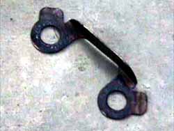
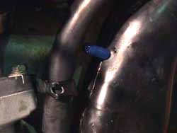
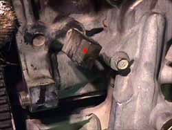
engine stand Procedure: 1. Remove theengine (Details). 2. Clean theengine, particularly the areas around the turbos to ensure no debris enterthe new turbo housings. Engine dergeaser or brake cleaner works well. On the driverside: 3. Remove theheat shield (3 x 10mm) (red dots in 1.). Remove the precat (2 x13mm nuts, 2 x 13mm bolts). 4. Remove theupper hardpipe & rubber hose coupling (1 x 10mm & 2 x hoseclamps)(2.). Remove the intake outlet (3 x 10mm & 1 x 10mm for waterfeed line bracket) (3.). Disconnect the boost solenoid vacuum linefrom the intake inlet. Remove the intake inlet (2 x 12mm). It's easy toget to this with an extension from the front. Disconnect the vacuum linefrom the wastegate actuator. 5. Trace thewater lines going from the turbo. They go from the sides of the turbo upwardto the block. Disconnect both rubber water lines (4 x hoseclamps), or cutthem if replacing (recommended). Note the shape and orientation of eachhose. Remove the water feed banjo bolt (1 x 19mm) on the outside of theturbo (red dot in 4.). Remove the bolt holding the line to the backof the block (1 x 10mm). Remove the ouside water line. 6. Remove the AC compressor bracket from the block (3 x 14mm, 1 x 12mm, 1 x 8mm). Removethe oil feed banjo bolt (1 x 19mm) from the block (red dot in 5.)behind it. Remove the midway oil feed line bracket on the motor mount (1x 14) (red dot in 6.). Loosen the oil feed line from the turbo (1x 12 tubing wrench). 7. Loosen thehoseclamps on the oil return line to the oil pan. 8. Bend backthe tabs on the turbo flange nut locking plates. The Nissan design on thesethings is poor. They should have made the tabs longer to allow gettinga screwdriver on them a little easier. Instead they are shorter then theheight of the nuts, making them difficult to pry back. Remove the turboassembly from the exhaust manifold (4 x 13mm). Remove the oil feed line(1 x 12mm tubing wrench). Remove the remaining water line from the turbo(1 x 19mm). Remove the oil return line (2 x 12mm) from the bottom of theturbo. 9. Installoil return line on bottom of new turbo with gasket (2 x 12mm), make sureit's pointing the right direction. Torque to 12-15 ft-lbs. 10. Installthe oil feed line (1 x 12 flare nut). Approximate the angle needed to fitthe lines back in place on the block. Tighten to 11-13 ft-lbs. There weretwo different models of oil feed tube available when I did my turbos, a1 piece (2/90+) and a 2 piece (7/89-2/90) version. I found the 2 pieceto be a little easier to work with. NOTE: Makesure the 10mm plug is in place in the bottom of the block area of the oilfeed line. It's very easy to overlook. 11 . Installthe inside water feed line (1 x 19mm banjo bolt). Make sure the tubingloop under the turbo is parallel with the housings. The heat shield willcradle it when it's installed. Torque to 11-14 ft-lbs. 12. Installthe outside water feed line (1 x 19mm banjo bolt). Get the bolt started,but leave the line loose, so it's mobile to get wrenches around to tightenthe mounting nuts. 13. Replacethe rubber coupling hose for the oil return line on the oil pan. 14. Installthe turbo and new metal gasket on the exhaust manifold, make sure to getthe oil return line in the rubber coupling hose. Hang the turbo by a singlenut on the rear of the flange. Tighten that nut to mate the flanges. Doublecheckall the line angles to make sure everything will fit properly. Make whateveradjustments necessary. 15. Installthe locking plate that doesn't look like the one in picture 7. (theone pictured is for the rear flange), on the front studs of the manifold,replace the mounting nuts (2 x 13mm). Use anti-sieze compound on the nuts.Snug them up. Remove the single nut from the rear of the flange, installthe locking bracket in picture 7. replace the rear mounting nuts(2 x 13mm). Torque all 4 nuts to 32-40. Bend the locking tabs down on thesides of the nuts. 16. Positionthe outer water feed line. Bolt the brace on the back of the block (1 x10mm bolt). Torque the banjo bolt (1 x 19mm) to 11-14 ft-lbs. 17. Bolt themidway oil feed line bracket on the motor mount (1 x 14) (red dot in 6.).Torque to 30-38 ft-lbs. The turbo needs to be primed with oil before initialoperation. Use an oil squirt can filled with standard motor oil (not synthetic,weight really doesn't matter) and start pumping oil into the end of theoil feed tube. Rotate the exposed turbo shaft from time to time until itfeels 'looser' from having oil around itself. Replace the banjo bolt atthe front of the oil feed line on the block (1 x 19mm). Torque to 11-14ft-lbs. 18. Replacethe AC compressor bracket (3 x 14mm, 1 x 12mm, 1 x 8mm). Torque the 14mm& 12mm bolts to 30-38 ft-lbs. Torque the 8mm bolt to 2.2-3.6 ft-lbs. 19. Installthe new rubber water lines, the slightly curved one goes on the side (2x hoseclamp), the straighter one goes on the back (2 x hoseclamp), anotherstraight one goes at the very front of the block, where the second metalline bends upward (2 x hoseclamp). We didn't do this one on Shahram's car.Just forgot about it until I sat down with the exploded diagrams ∂ numbers. 20. Tightenthe hoseclamps on the rubber coupling hose for the oil return line on theoil pan. 21. If installingan EVC, or if an EVC is already installed, now is the time to remove theboost solenoids (8.). They're unplugged and useless with a properlyinstalled EVC. Remove the T in the vacuum & prep the vacuum line togo straight from the wastegate nipple to the front intercooler hardpipe.Something interesting, this hose is the same one the boost jet would goin. If you look at it close enough, there's a factory orifice already inthe line, it allows the car to reach factory set 9psi! 22. Clean oldgasket material off the intake outlet. Install the intake outlet (3 x 10mm),with new gasket. Re-connect the water feed line bracket. Torque all to4.6-6.1 ft-lbs. Install new intake outlet rubber hose coupling (hoseclampassembly or 2 hoseclamps, depending on if the assembly is still together).Leave clamps loose. Install the intake hardpipe in the other end of thecoupling, bolt to plenum (1 x 10mm). Tighten the hoseclamps (2.).Stuff a rag in the open end to keep debris from entering the turbo. 23. Installthe intake inlet (2 x 12mm), with gasket. Torque to 18-22 ft-lbs. Re-connectthe vacuum line from the boost solenoid. If running an EVC fulltime, cap the nipple instead (9.). Stuff a rag in the openend to keep debris from entering the turbo. 24. Installthe pre-cat and gasket (2 x 13mm nuts, 2 x 13mm bolts). Use anti-seizecompound on the nuts & bolts. Torque to 18-22 ft-lbs. Install the heatshielding (3 x 10mm) (1.). Torque to 4.6-6.1 ft-lbs. On the passengerside: 25. Removethe heat shield (3 x 10mm) (red dots in 10.). Remove the precat(2 x 13mm nuts, 2 x 13mm bolts). 26. Removethe upper hardpipe & rubber hose coupling (1 x 10mm & 2 x hoseclamps).Disconnect the vacuum line from the intake inlet. Remove the intake inlet(2 x 12mm). 27. Trace thewater lines going from the turbo. They go from the sides of the turbo upwardto the block. Disconnect both rubber water lines (4 x hoseclamps), or cutthem if replacing (recommended). Note the shape and orientation of eachhose. Remove the bolt in the rear water feed line's upper bracket. 28. Removethe oil feed banjo bolt (1 x 19mm) from the block (11.) behind it.Remove the oil feed line from the turbo (1 x 12 tubing wrench) (12.).Note: on the oil line this side got insulated in mid '92. So don't be surprisedwhen the new part has insulation on it & the old one doesn't. All newlines sold have it. 29. Removethe lower oil return tube (2 x 12mm, 1 hoseclamp on oil pan end). 30. Twist theoil feed block coming from the block to allow room for the turbo flangeto clear (red dot in 13.). 31. Bend upthe locking plate tabs. Remove the turbo (4 x 13mm), use a wrench on theback two nuts & outside front (14.). Use a socket on an extensionfrom below to get the last one. 32. Removethe intake outlet (3 x 10mm & 1 x 10mm for water line bracket). Removethe heat shield bracket from the compressor side of the turbo (2 x 10mm)(red dots in 15.). 33. Removewater feed lines from the turbo (2 x 19mm banjo bolts). 34. Installwater lines on new turbo (2 x 19mm banjo bolts). Don't tighten them yet.The short one should be installed with the hose leaning outward, not inward.It should line up right next to the rear water feed line. Install the wastegatevacuum line (1 hoseclamp). Make whatever adjustments needed like the driver'sside to accomodate an EVC if one is being used. Make sure the stock orificementioned in the driver's turbo install is used in both sides. 35. Clean offold gasket material from intake outlet. Install intake outlet (3 x 10mm).Bolt front water feed line to intake outlet (1 x 10mm). Torque all to 4.6-6.1ft-lbs. Remove the oil pressure sensor from the oil filter bracket belowthe turbo. 36. Hang theturbo off the flange with gasket using the single nut technique from abovefrom one of the rear studs. Put on the front locking plate & snug upthe front nuts (2 x 13mm). Remove the single nut from the rear stud. Installthe rear locking plate & nuts (2 x 13mm). Use anti-seize compound onall nuts. Torque all to 32-40 ft-lbs. 37. Installthe new rubber water lines, the double 90 degree bend goes on the frontwater feed line (2 x hoseclamp), the double angle one goes on the rearwater feed line with the yellow dotted end going to the front/top (2 xhoseclamp) (16.). 38. Re-attachthe bracket on the rear water feed line. Tighten the water feed line banjobolts (2 x 19mm). Torque to 11-14 ft-lbs. 39. Removeold oil return line rubber coupling (1 x hoseclamp). Replace the rubbercoupling hose for the oil return line on the oil pan (2 x hoseclamp). Installthe oil return tube (2 x 12mm, 1 hoseclamp) and gasket. Torque bolts to12-15 ft-lbs. 40. Twist theoil feed block coming from the block back to horizontal (red dot in 13.).Start the front fitting of the oil feed line into the top of the turbo.Prime the turbo with oil just like the driver side. Install oil feed tubebanjo bolt (1 x 19mm banjo bolt). Note: This is the set of copper sealsthat has the 'bridge' on it. Torque to 11-14 ft-lbs. Tighten the frontfitting (1 x 12 tubing wrench). Torque to 11-13 ft-lbs. 41. Installthe heat shield bracket to the compressor side (2 x 10) (17.). Torqueto 18-22ft-lbs. This seems excessive, but that's the spec. in the '95 manual.They really don't want the shield coming off! 42. Installthe intake inlet (2 x 12mm), with gasket. Torque to 18-22 ft-lbs. Cap offvacuum nipple, or re-attach to the stock boost solenoid, depending on needs.Re-connect the vacuum line from the boost solenoid. If runningan EVC full time, cap the nipple instead (9.). Stuff a ragin the open end to keep debris from entering the turbo. 43. Installnew intake outlet rubber hose coupling (hoseclamp assembly or 2 hoseclamps,depending on if the assembly is still together). Leave clamps loose. Installthe intake hardpipe in the other end of the coupling, bolt to plenum (1x 10mm). Tighten the hoseclamps. Stuff a rag in the open end to keep debrisfrom entering the turbo. 44. Installthe pre-cat and gasket (2 x 13mm nuts, 2 x 13mm bolts). Use anti-seizecompound on the nuts & bolts. Torque to 18-22 ft-lbs. Install the heatshielding (3 x 10mm) (10.). Torque to 4.6-6.1 ft-lbs. 45. Don't forgetto tighten the intake outlet clamps when the engine is going back intothe chassis. Rev. 5-9-2000 |