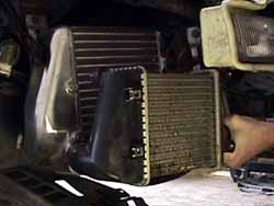
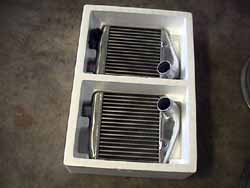
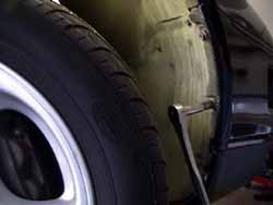
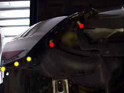
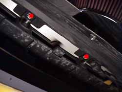
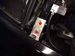
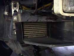
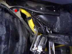
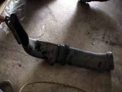
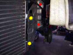
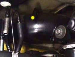
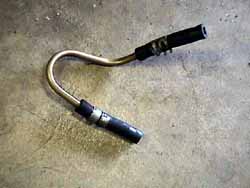
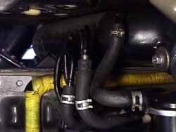
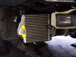
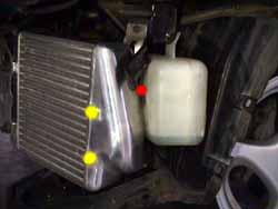
| Somewhere along the upgrade path, the stock intercoolersare going to have to be replaced. The stock intercoolers are very smalland rather cheaply built with plastic endcaps. Aftermarket intercoolersare substantially larger and are fully aluminum (1. & 2.).Like the injectors, they do the job well for a stock car, but after a fewmods, they cannot support the airflow required to produce those 375rwhp+numbers. Unlike the injectors, the addition of upgraded intercoolers generallydoesn't do much for the overall power output immediately. It's probablyone of the most 'building blockish' upgrades along the path. Not much gain,but a necessary evil to make all the other mods really come together. Theintercoolers exist to cool the air charge after it has come out of theturbo on it's way to the engine's intake. A cooler/denser air charge increasesthe amount of oxygen in a given volume. More oxygen plus more fuel equalsmore horsepower. This install is of the HKS intercoolers on a '94TT. Timing: Some stage charts put them pretty early in the order, others put themlater. I think it needs to happen at the same time the injectors are upgradedor at most a step before. Larger injectors equals more boost potentialand upgraded intercoolers are neccessary to get the larger air volume ascool as the lesser stock air volume was before. Special tools: 12mm Gear Wrench Procedure: 1. Disconnect the negative terminal (1 x 10 mm) of the battery.Jackup the front of the car and place it on jackstands. Use a china markerto 'stripe' the facia/fender joint. This indexing will help get thejoint aligned properly when putting the facia back on. 2. Remove the centerpanel (2 or 4 x 10 mm depending on year). 3. Remove the front black splash shielding (lot of screws & bolts& stuff. keep close track of what goes where). There's a couple boltsup high but are covered by the side splash shields. Remove all bolts alongthe bottom of each side splash shield. 4. Turn the front wheels all the way to the left. Remove the bolts inthe passenger front wheel liner (4 x 10 mm) and bend it back/down (3.) 5. Remove the bolts holding the side of the facia to the fender (3 x10mm) (yellow dots in 4.). Remove the bolt holding the metal faciabacking to the brace (1 x 10mm). 6. Remove the corner lamps (2 x phillips). Disconnect the electricals. 7. Through the hole where the corner lamp was, remove the nuts holdingthe corner of the facia onto the fender (2 x 10 mm nuts) (red dots in 4.). 8. Repeat steps #4 - 7 for the driver side. Use a 10mm short socketon a swivel and extension to get to the bolt holding the metal facia backingto the brace (1 x 10mm). 9. Remove the bolts holding the facia to the bottom of the bumper (2x 10 mm bolts) (5.). Remove the bolts holding the facia to the frontof the frame (4 x 10 mm bolts) (6.). Hold the facia in place andthen gently remove it. The brackets the bottom two bolts were run throughmight make it a bit challenging. Be extremely careful not to scratch thepaint on the facia with the 4 studs sticking out from the fronts of thefenders. 10. Remove the shrouds on the ICs (2 x 10 mm bolts & 2 x phillipsplastic clips each side) (7.). 11. For the HKS (& Stillen?) ICs, the air intake ducts will needto be removed. Remove the bolt holding them in place (1 x 10 mm)on each side (8.). If a K&N type intake or something else besidesthe stock airbox isn't installed by now, it needs to be. Remove the ductsby pulling them straight out (9.) 12. On the passenger side, loosen the clamps for the hoses coming inand out of the ICs (2 x 8 mm). Remove the IC by removing the single boltfrom the backside & unbolting the mounting bracket from the frame onthe front (3 x 12 mm bolts) (red dots in 10.). 13. Remove the mounting bracket from the stock IC and bolt it onto theaftermarket IC tightening finger tight (2 x 12 mm bolts) (yellow dots in10.). Fit the IC into the intake hoses and push it into place. Fingertighten the mounting bracket bolts back on the frame. Finger tighten thebolt to the back of the intercooler. Tighten all the bolts once everythingis in place (5 x 12 mm bolts). 14. On the driver side, loosen the clamps for the hoses coming in andout of the ICs (2 x 8 mm). Remove the bolt holding the outside of the coolantoverflow reservoir to the hanging bracket. This allows access to the rearmounting bolt for the IC. If a 12mm Gear Wrench is available, this willgo quickly, otherwise just work with a regular wrench. Remove the IC byremoving the single bolt from the backside (1 x 12 mm bolt) . Unbolt themounting bracket from the frame on the front (2 x 12 mm bolts). 15a. If installing a 'taller' IC, on the driver side, remove the metaltubing loop from the intake tracting to the carbon canister and it's rubbercouplings (11. & 12.). Bend the other 3 metal tubes upwardto make room for the IC to fit in front of the carbon canister (13.).Supposedly this is easy to relocate. I examined it for a few minutes &decided it was easier to just bend the tubes up out of the way. Once allthe metal loops are bent straight up and angled back a bit as they cometo the outside of the car to match the angle of the IC, take some extra1/4" vacuum line and conntect it to the intake tracting with a clamp, thenloop it around and cut it off at the carbon canister nipple. Attach itto the carbon canister and clamp it too. 15b. I'm not sure how to deal with the 'thicker' ICs in this situation.The HKSs are right up against the carbon canister and the coolant overflowreservoir. They have to be thicker coming forward, not backward since there'sno room. The tubes on the carbon canister shouldn't be a problem. 16. Remove the mounting bracket from the stock IC and bolt it onto theaftermarket IC tightening finger tight (2 x 12 mm bolts). Fit the IC intothe intake hoses and push it into place. Finger tighten the mounting bracketbolts back on the frame. Finger tighten the bolt to the back of the intercooler.Tighten all the bolts once everything is in place (5 x 12 mm bolts). Therear mount bolt is easily done with a Gear Wrench (red dot in 15.).There are no toque specs for any of the mounting bolts. I'd recommend 9-12ft-lbs. Reattach the coolant overflow reservior to the bracket ( 1 x 10mm bolt). 17. If installing a 'taller' IC, either the original shrouds can beput back on, effectively wasting the extra surface area, or left off &have the air spill around it. I'd opt for the spill around option. Thereare sets of modified shrouds being made to fit the taller ICs. I'm goingto mod a set myself & put the info in here when I do. If it's a 'thicker'IC, like the GReddy, then just put the shroud back on. Either way, make*sure* the holes on the endcaps are filled with the bolts.. otherwise therewill be a huge boost leak in the pressurized section of the intake tracting(yellow dots in 14. & 15.). 18. Reinstall the front facia in reverse order of it's removal. Thereare no torque specs for any of the front bolts. I'd recommend 9-12 ft-lbson anything with real machined threads. Published 2-16-01
|