This article details the process of putting anewly rebuilt engine back together. It starts with a prepped blockstraight from the machine shop and proceeds all the way throughstarting the car for the first time. | | |
Parts- Nissan rebuild gasket kit (Image 0)
- Permatex Ultra Copper High Temp RTV Silicone Gasket Maker (orange)
- Permatex Ultra Blue Sensor-Safe RTV Silcone Gasket Maker (blue)
- Assembly lube, if assembling the heads/lifters/cams
| | Image 0. |
Tools- 3/8 in socket drive and extensions
- 10mm socket/wrench/gear wrench
- 12mm socket/wrench/gear wrench
- 13mm socket/wrench/gear wrench
- 14mm deep well socket
- 17mm socket
- 19mm socket
- 5mm allen head socket or wrench (socket preferred)
- 6mm allen head socket or wrench (socket preferred)
- Torque wrench that supports 10 ft.lbs. to 150 ft. lbs.
- Large Philips head screwdriver
| |
|
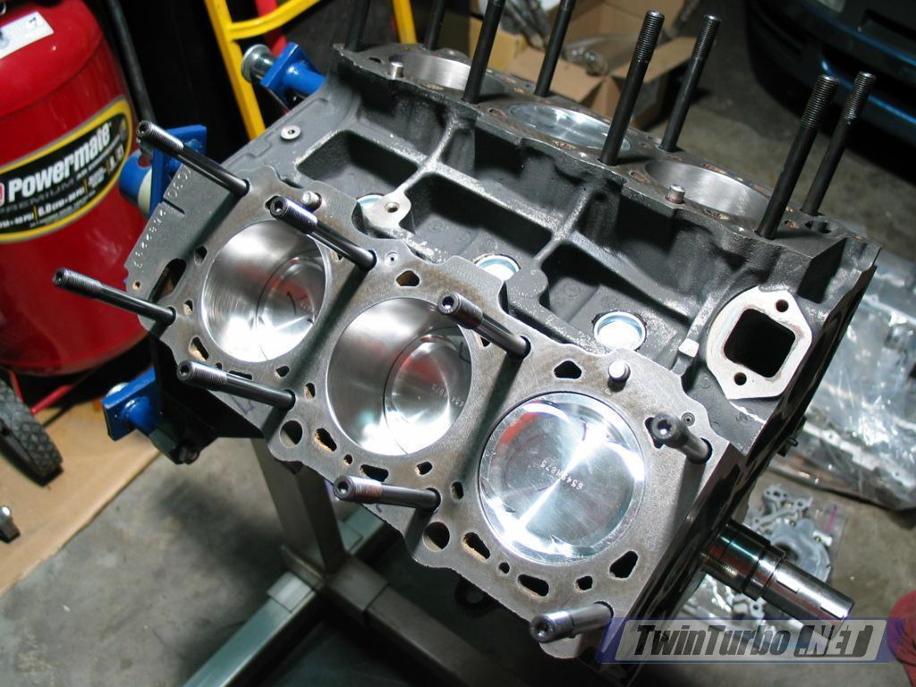
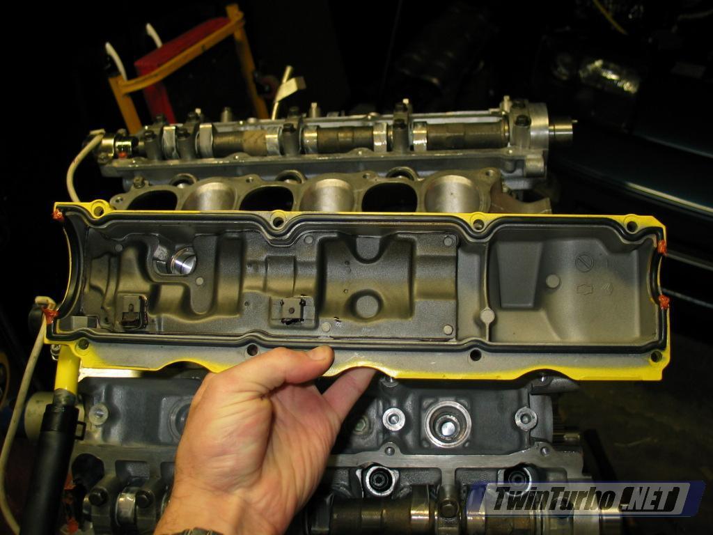
AssumptionsThis tech page is based on the rebuild of my highly modified '93 TT.This vehicle has no EGR or AIV and has had a throttle body water bypassdone on it with all other vacuum lines under the plenum re-routed. Ifyou use this page, be aware of these differences and handle theaffected areas according to your build. This article starts with a prepped block that has only pistons/rodsand crank/crank girdle installed. In addition, I am using ARP headstuds which were already screwed into the block, rather than stock headbolts. (see Image 1) The vehicle has Jim Wolf Sport600 turbos, Specialty-Z divorced downpipes, testpipes, and a dual MAFS setup. Finally, the heads were also machined and I got them back with thevalves installed, but no lifters or cams so the final assembly of theheads is covered in this article. | | Image 1. |
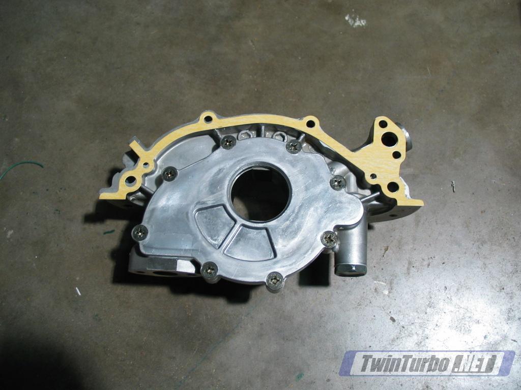
Step 1: Install oil pump. Service Manual Reference: EM-43 LC-5
Image 2 shows the oil pump and new gasket.- Install gasket (15066-30P00) onto block using the positioning pins to hold it in place.
| | Image 2. |
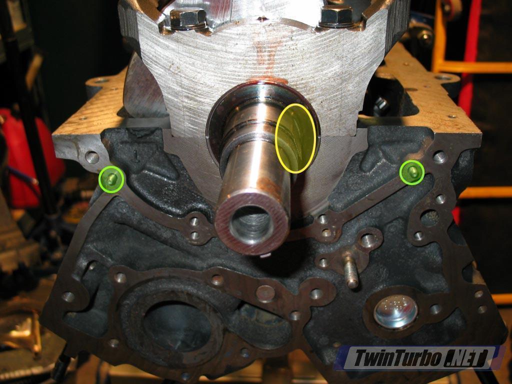
- Line up the crankshaft with the hole in the oil pump. There areflat spots on the crank that need to be aligned before the oil pumpwill slide on. (yellow in Image 3) Position the oil pump on the positioning pins. (green in Image 3)
| | Image 3. |
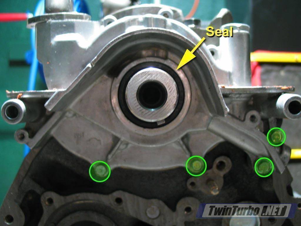
- Bolt down the oil pump. There are 4 10mm bolts. 2 on the top of theoil pump (bottom if you have engine upside down), and two that goaround the pump outlet. (green in Image 4) The outer two holesare mounting points for the compressor and alternator and are not usedright now. Torque the bolts to 4.6-6.1 ft lbs (0.64-0.85 kg-m).
- Install the front oil pump seal provided in the gasket kit.Place the open (spring) side toward the oil pump and slip it over thecrankshaft. Get it roughly in place and then put the old seal (if youstill have it) over the new one and use a blunt object like a punch toknock the seal into place, using the old seal to absorb the blows. Image 4 shows the seal in place.
| | Image 4. |
Step 2: Install rear oil seal retainer.Service Manual Reference: EM-43
- Install gasket (12279-18V00) onto block using the positioning pins to hold it in place. (Image 5 shows the retainer and gasket)
| | Image 5. |
- Install the rear oil seal retainer onto the positioning pins. (green in Image 6)
| | Image 6. |
- Install 4 bolts using 4.6-6.1 ft. lbs. (0.64-0.85 kg-m) I foundthat a 10mm gear wrench works well here as the engine stand leaveslittle clearance in the back. (Image 7)
| | Image 7. |
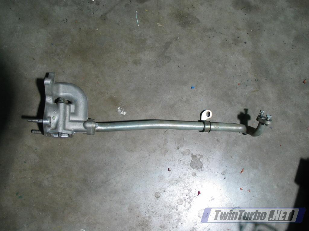
Step 3: Install oil pickup/strainer.Service Manual Reference: EM-43
- Check strainer for foreign debris. Clean off any gunk from the screen inside. (Image 8 shows the strainer)
| | Image 8. |
- Install new O-ring (15053-F6500) onto the end of the strainer. (Image 9 shows O-ring location)
- Install oil pickup using two bolts into the block and twobolts for the supports. The two bolts at the tail of the strainer use12-15 ft. lbs (1.6-2.1 kg-m) (green in Image 9) and the two support bolts use 4.6-6.1 ft. lbs. (0.64-0.85 kg-m) (yellow in Image 9)b
| | Image 9. |
Step 4: Install oil pan. Service Manual Reference: EM-43, EM-11
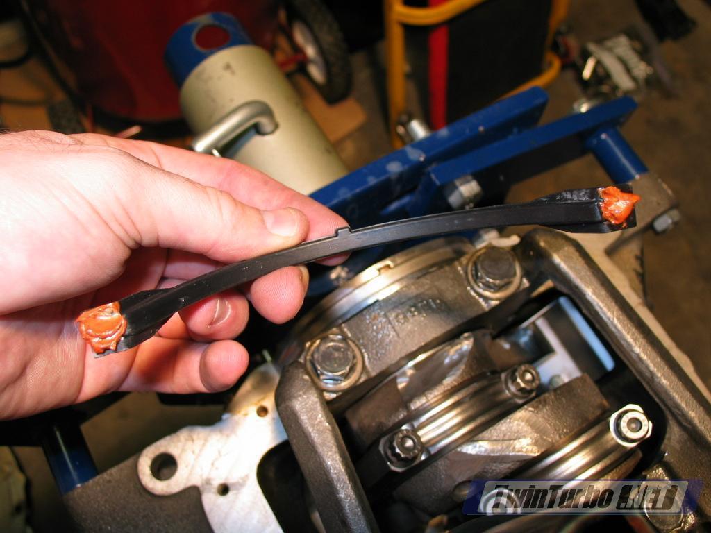
- Install the two oil pan gaskets onto the oil pump (front:11121-14Y00) and rear oil retainer (rear: 11121-14Y10) using a smallamount of orange RTV on the edges of each to hold it in place and sealthe corners. (Image 10 shows RTV application and Image 11 shows installed gasket)
| | Image 10.Image 11. |
- Install a solid bead of Orange RTV around the oil pan. Do NOTinstall RTV on the holes for the crankshaft (that seal will be coveredby the gaskets). In general, don't skimp on liquid gasket. It's betterto have to clean up excess that gets smashed out than end up with aleak later. (Image 12)
| | Image 12. |
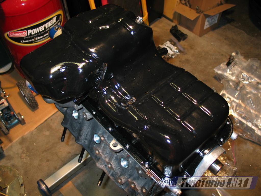
- Install the oil pan with 17 10mm bolts. Be careful when placing thepan over the crank girdle and try to avoid bumping the girdle as gasketmay smear off of the pan. Torque all bolts to 4.6-6.1 ft lbs (0.64-0.85kg-m) Note: The service manual shows 18 bolts but at least in the case of my 93 there are only 17 bolts. (Image 13)
- Remove excess RTV from the outside of the oil pan. Best to wait for it to dry and then peel off the excess.
The bottom of the engine is complete! Flip the engine over and continue. | | Image 13. |
Step 5: Install the detonation sensorInstall on the top of the block, using a 12mm bolt. Position the sensorso that the harness connection is facing the rear of the block. (Image 14) Connect the harness (not pictured) | | Image 14. |
Step 6: Install thermostat housing and upper water pipeService Manual Reference: LC-9
These two pipes are normally not separated. If yours are then reconnectthem first using the 2 bolts and blue liquid gasket on the matingsurfaces.
Image 15 shows the thermostat housing and upper water pipe. | | Image 15. |
- Put a blue RTV around the base of the thermostat housing. (Image 16)
| | Image 16. |
- Install the thermostat housing and upper water pipe using 2 12mm bolts. Torque to 12-15 ft. lbs (1.6-2.1 kg-m) (Image 17)
| | Image 17. |
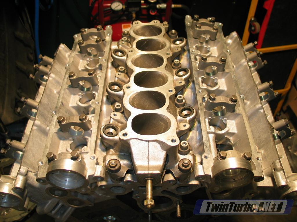
Step 7: Install the headsService Manual Reference: EM-23
- Install new head gaskets from the gasket kit (Image 18)
- Install each head, making sure that the positioning pins (yellow in Image 18) line up and the head slides onto them properly.
| | Image 18. |
- This rebuild is using ARP head studs. If you are using studs andthey are already in place, it will be a bit tricky to get the heads toclear the thermostat housing. In this case, I used a dremel to sand offsome of the corner that interferes with the housing on the passengerside. (Image 19) On the driver side, just hit the edge of the head with a rubber mallet and it will slide past.
- Install head bolts, or washers/nuts on head studs. Screw themin lightly at first. If you are using ARP studs, you need to coat thewashers with provided ARP assembly lubricant. Just squirt the lube outon a piece of cardboard and dunk each washer into it to make sure it iswell coated. (Image 20)
- Use angular torquing method on heads which means torque toapprox 60% of goal on all bolts in pattern and then repeat procedureincrementing by 10 ft lbs each time until you reach spec torque of 90ft lbs. I started at 50 and worked up through 60, 70, 80, and then 90.For head bolts, the manual states to start at 29 ft-lb on each, then gostraight to 90 ft lb. Loosen all bolts completely, and then do itagain. Torque in the order shown in Image 18 for the driver'sside head. The same pattern is used on the passenger head.with 5 &8 being at the back of the engine and 6 & 7 at the front.
- Don't forget the two small M6 bolts. One on each head. Torque to 7-9 ft. lbs. (1.0 - 1.2 kg-m)
| | Image 19.Image 20. |
Step 8: Install the lower intake. Service Manual Reference: EM-8
Install lower intake gaskets from the gasket kit. (Image 21) | | Image 21. |
- Install lower intake. Torque down in two steps. First step torquebolts and nuts to 2.2-3.6 ft. lbs (0.3 - 0.5 kg-m). Second step torquebolts to 12-14 ft.lbs. (1.6-2.0 kg-m). Torque the nuts to 17-20 ft.lbs.(2.4-2.8 kg-m) (Image 22)
| | Image 22. |
Step 9: Install motor mountsCheck the rubber part of the motor mounts and verify that they haven'tseparated or started to split in two. If one has, replace the mount(about 80 bucks).Install each motor mount using 4 14mm bolts and torque down tight. Image 23 shows the passenger side mount. | | Image 23. |
Step 10: Install oil filter tree
Service Manual Reference: EM-6
- Install lower transmission brackets on both sides of the block.
- remove any old gasket from the edge of the tree.
- Check condition of the rubber O-ring inside the tree. (Image 24) This ring is not part of the rebuild kit, so replace separately if necessary.
- Install tree with new paper gasket from gasket kit. Torque bolts to 12-15 ft.lbs. (1.6-2.1 kg-m) (Image 25 shows mounting location on the rear passenger side of the block.
| | Image 24.Image 25. |
Step 11: Install Alternator bracket Service Manual Reference: EM-6
Install the bracket with 3 14mm bolts, torquing to 12-15 ft.lbs. (1.6-2.1 kg-m) Inset in Image 26 shows bracket. Yellow indicates mounting points. | | Image 26. |
Step 12: Install dipstick tube - Position the dipstick tube over the hole in the bottom of the block. (yellow in Image 27)Make sure that the tube bracket is facing the right direction totighten down on top of the exhaust valve cover in the 2nd hole from therear (green in Image 27 with arrow indicated final position after valve cover installation).
- Push the dipstick down into position. You may need to tap it the rest of the way in with a rubber mallett until it seats fully.
| | Image 27. |
Step 13: Install exhaust manifolds Service Manual Reference: EM-6
- Install new manifold gasket from gasket kit. (Image 28)
- Install manifold. Torque nuts to 17-20 ft. lbs. (2.4-2.8 kg-m)
| | Image 28. |
- Install manifold heat shields with 10mm bolts. (Image 29)
- Repeat for other side.
| | Image 29. |
Step 14: Install lifters if required Service Manual Reference: EM-23
If your heads are partially assembled, this step walks through final assembly.- Put small amount of assembly lube into each shaft to protect lifters on initial startup. (Image 30)
| | Image 30. |
- Slide lifter into shaft with smooth side up (6 lifters per cam) (Image 31)
| | Image 31. |
- Make SURE that the cam journals are stamped. The order andorientation of the journals MUST be the same as when it wasdisassembled. In most cases, the machine shop will stamp numbers intothe journals (i.e. E1, E2, etc.) to note which position and directionthe journal cap should be reinstalled. (Image 32 shows stamp onend journal cap). Remove each journal cap for a single cam (5 total)and set them aside. I checked the bolts in each cap and found that theywere a bit gunked up and did not move freely inside the cap, so Ipulled each bolt out, cleaned it, and put some Liquid Wrench in thehole of the cap to allow the bolt to move freely.
- Install the cam. The cams are different lengths as one headis longer than the other. On each, the exhaust cam has a bigger endwhere the sprocket attaches to, with 4 thread holes in it. The intakehas a smaller mount point for its sprocket.
- Put assembly lube on the bottom of the journals and then press the camshaft into place.
- Put assembly lube on each journal cap and reinstall them in the same position and direction that they were removed.
- Put assembly lube on the cam lobes to protect them for initial startup as well.
| | Image 32. |
- Replace each cap IN THE SAME POSITION AND ORIENTATION THAT IT WAS REMOVED.Torque the caps to 6.7 - 8.7 ft. lbs.
- Repeat all steps for the 3 remaining cams. (Image 33 shows completed heads)
| | Image 33. |
Step 15: Install VTC solenoids and rubber plugs Service Manual Reference: EM-23
- Install the two VTC solenoids with 2 10mm bolts. The solenoid withthe shorter cable goes on the driver's side head. Put a bead of orangeRTV on the underside of the solenoid to seal it to the head. Torquebolts to 12-18 ft.lbs. (1.6-2.5 kg-m) (Image 34)
| | Image 34. |
- Install the half-moon rubber plugs in the exhaust side of theheads. Use orange rubber gasket on the bottom of the plug to seal it tothe head. (Image 35)
| | Image 35. |
Step 16: Install Intake Valve covers Service Manual Reference: EM-23
The intake cover with the oil cap goes on the passenger side.- Install new rubber gasket from the gasket kit on the underside of the valve cover. (Image 36)
- Apply small dot of orange liquid gasket to the edges of each end (around the VTC and the cam sprocket) to seal well. (Image 36)
| | Image 36. |
- Install 8 intake cover screws and tighten to 0.7-2.2 ft. lbs(0.1-0.3 kg-m). Basically screw them down reasonably tight with aPhilips head screwdriver.
- Repeat for the other side. (Image 37 shows both covers installed)
| | Image 37. |
Step 17: Install Exhaust Valve coversService Manual Reference: EM-23
- Remove all old liquid gasket residue from the covers.
- Lay a bead of orange liquid gasket around the base of the cover following the groove. (Image 38)
- Install the cover on the head.
| | Image 38. |
- Tighten all 10mm bolts to 4.6-6.1 ft. lbs. (0.64 - 0.85 kg-m) Onthe driver's side, make sure to place the dipstick tube clamp OVER thevalve cover second hole from the rear and secure with the valve coverbolt.
- Make sure that you have both front intake valve cover vent hoses installed and clamped down. (Image 39)
| | Image 39. |
Step 18: Install coil pack guides- Make sure the end of each guide has a brown rubber cap installed on the end. (Image 40)
| | Image 40. |
- Install each guide on appropriate head. Tighten 4 12mm bolts appropriately. (Image 41)
| | Image 41. |
Step 19: Install fuel rail Service Manual Reference: EM-8
Thisstep assumes that your injectors are already installed in the fuelrail. If they are not, install injectors into the fuel rail beforecontinuing with this step.- Make sure that the black rubber injector insulators are already placed in the lower intake (visible in Image 22)
- Position fuel rail in place over the lower intake, matching each injector tip into it's appropriate hole.
- Tighten the fuel rail down with 6 10mm bolts (yellow in Image 42. No torque spec is given in the service manual so just make sure they are reasonably tight.
- Fasten the grounding strap from the fuel rail to the rear of the lower intake on the driver's side. (green in Image 42)
| | Image 42. |
Step 20: Install front water pipes Service Manual Reference: LC-9
- Apply blue liquid gasket to the metal flanges on the water pipes. (Image 43)
| | Image 43. |
- Install water pipes using 2 10mm bolts each. Tighten bolts downappropriately. No torque specs are given in the service manual. (Image 44)
| | Image 44. |
Step 21: Install cam seals Service Manual Reference: EM-23
- Install each cam seal with the open (spring) side toward the block. (Image 45)
| | Image 45. |
- Put the new seal on the cam and then put an old one on top of it to absorb the tapping. (Image 46)
| | Image 46. |
- Use a blunt nosed punch or other blunt instrument against the oldseal and tap the new one into place, fully seated against the block andfront cam journal cap.
- Repeat for each of the 4 cam seals. (Image 48 shows all seals in place)
| | Image 47.Image 48. |
Step 22: Install the crankshaft timing sprocket.- Slip the sprocket backing plate over the crankshaft lining the key up with the slot in the plate. (Image 49)
- Put sprocket on end of crankshaft and line up the keys withthe slot in the sprocket. Use a rubber mallet to tap the sprocket intoplace at the back of the crankshaft (on top of the second key). (Image 49)
| |
|
Step 23: Install timing belt backing plates.Service Manual Reference: EM-12
- Start with the drivers side backing plate. The rebuild gasket kithas replacement rubber inserts for the backing plates. Install new onesfrom the kit if necessary. Use 4 10mm bolts to fasten the driver's sideplate to the block using 4.6-6.1 ft.lbs. (0.64-0.85 kg-m) (Image 50)
- Install the passenger side plate using 4 10mm bolts to fasten it in place at 4.6-6.1 ft.lbs. (0.64-0.85 kg-m) (Image 50)
| | Image 49. |
Step 24: Install idler pulleysService Manual Reference: EM-12
- Install lower idler pulley on the driver's side using 32-43 ft.lbs.(4.4-5.9 kg-m) torque on the nut. In my case I replaced the nut andstud with a long hex bolt of same grade steel. (yellow in Image 51)
- Install upper idler pulley on stud. Torque nut to 32-43 ft.lbs. (4.4-5.9 kg-m) (green in Image 51)
| | Image 50. |
NOTE: The next several steps are covered in detail in the timingbelt replacement tech page. This document does not go into as muchdetail, so please refer to the timing belt replacement page to makesure you have all your bases covered on the timing belt
Step 25: Install Exhaust cam sprockets Service Manual Reference: EM-12
- Place sprocket on alignment pin. Attach 4 11mm bolts through the 4hole plate and onto the sprocket. Torque to 10-14 ft. lbs. (1.4-1.9kg-m) (Image 52 shows completed install)
- Repeat for other exhaust sprocket.
| | Image 51. |
Step 26: Install intake sprockets. Service Manual Reference: EM-12
- Place sprocket with slot in inner core aligned with the alignmentpin on the cam. Slide the sprocket into place over the alignment pin.
- Install main 19mm sprocket bolt into the sprocket and torquedown to 90-98 ft. lbs. (12.5-13.5 kg-m) Use wrap method discussed intiming belt tech page. (Image 53 shows belt wrap method for passenger side intake sprocket and Image 54 shows wrap method for driver's side.)
- The covers for the intake cam sprockets should also beinstalled after torquing the sprockets down. Install the spring andthen the cover using 4 8mm bolts. Refer to the timing belt replacementtech page for details.
| | Image 52.Image 53. |
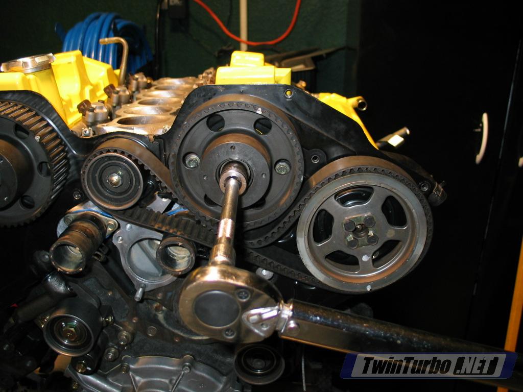
Step 27: Install timing belt- Use the timing belt replacement page to see how to line up /install the belt. You will probably have to twist the cam sprocketsmanually to get them lined up as they will be in no particular positioninitially.
| | Image 54. |
Step 28: Install auto-tensioner (only after belt is in place) NOTE: do NOT use this as a proper guide for setting up theauto-tensioner and verifying proper timing belt installation. Refer tothe timing belt replacement tech page for detailed instructions.- Install tensioner over stud in block and attach nut and washers. (green in Image 56)
- Push tensioner into place with belt located properly on thepulley. Line the slots in the tensioner up with the bolt holes in theblock and screw in 2 12mm bolts. (green in Image 56)Torque all to 12-15 ft.lbs. (1.6-2.1 kg-m)
| | Image 55. |
Step 29: Install water pump- Put blue permatex on the backside of the water pump (Image 57)
| | Image 56. |
- Image 58 shows water pump position. Install all bolts. The stud goes on the furthest right upper hole. (green in Image 59) Torque to 12-15 ft. lbs.
| | Image 57.Image 58. |
Step 30: Install lower timing belt cover- Positioned the lower cover where the holes in the cover line up with bolt holes in the block.
- Attach cover with 5 bolts using a philips head screwdriver.The short bolt that goes in the furthest right upper position (green inImage 60) cannot be bolted in until the AC tree is attached tothe block later. (The AC tree is shown attached in the image, butshould not be at this point).
| | Image 59. |
Step 31: Install passenger side upper timing belt cover- Make sure the one stud behind the cover is installed into the block
- Attach cover with 6 bolts using both 5mm hex socket andphilips head screwdriver. The shortest bolt goes in the leftmost lowerhole. (Image 61)
| | Image 60. |
Step 32: Install the Crank Angle Sensor- Line the CAS up with the exhaust sprocket. There is a notch insidethe sprocket that must be aligned with the CAS for it to slip intoplace.
- Attach the CAS with 3 12mm bolts and tighten down.
| | Image 61. |
Step 33: Install driver's side upper timing belt cover- Follow the same procedure as for the passenger side cover.
| | Image 62. |
Step 34: Install upper and lower front water pipesService Manual Reference: LC-9
- Install thermostat. Put small bead of blue RTV around the back ofthe thermostat. Place thermostat into housing on front of engine. Makesure the edge marked 'Top' is at the top. (64.)
| | Image 63. |
- Put a bead of blue RTV around the lower water pipe. It doesn't takemuch to get a good seal and you don't want too much excess to spillinto the passageways. (64.)
| | Image 64. |
- Install lower water pipe with 2 12mm nuts and 1 6mm hex bolt. Tighten all to 12-14 ft.lbs. (1.6-1.9 kg-m) (65.)
- Position hose clamps on the upper rubber hoses. Be VERYcareful with clamp position so you can get to them after the pipe isinstalled. The pass side front clamp should be facing up. The driver'sside front clamp should be down and to the right. The proper positionsare highlighted in green in (65.)
| | Image 65. |
- Put blue RTV bead around the center base of the upper water pipe.Install outer ends into the two hoses and seal against the block. Movethe hose clamps into final position on the pipe before installing thebolts so you have some play to work with. Install 3 6mm hex bolts andtorque to 12-15 ft.lbs. (1.6-2.1 kg-m). (66.)
| | Image 66. |
Step 35: Install turbosService Manual Reference: EM-7In my case, the turbos were removed complete before the rebuild, sothere are no steps to putting the turbos back together. This rebuild isusing Jim Wolf Sport600 turbos, so heat shields and some brackets arenot used. If you are using stock turbos, refer to the service manualdiagrams to make sure you have all parts correctly installed. Passenger side turbo- To get the turbo into 'initial' state for installation make sure that the following parts are already installed on the turbo: (67.)
- upper air inlet
- oil return tube
- long water tube
- short water tube
- It's easiest for installation if you move the rubber hose thatconnects the oil return pipe to the oil pan onto the oil return pipe.Use a little Liquid Wrench/WD40/PB Blaster on the hose to allow it toslide easily onto the return pipe. Make sure that the ENTIRE hose is onthe return pipe with no overhang to avoid binding up with the oil paninlet during installation.
| | Image 67. |
- Put a small amount of orange RTV on the threads of the oil feedadapter and Install it into the block. Screw it in but leave it pointedstraight down temporarily to help with the turbo fitment. (68.) shows adapter in final position.
| | Image 68. |
- With Sport600's I found that it's best to release the motor mountand just leave the lower leftmost bolt in, but loose. Allow the mountto swing down and out of the way of the turbo.
- Install turbo onto manifold flange using a new metal gasketfrom the rebuild kit. Install the locking plates before placing 4 13mmnuts on the studs. (69.) There is no magic trick here besidespatience. Get the outside rear nut on first to hold the whole thing inplace, then the inside rear nut. The inside front nut can be attachedby using a 13mm socket with a long extension and snaking it up from thebottom. The outside front nut just has to be done by hand and takessome patience.
- Tighten the bolts down to 32-40 ft. lbs. which just meanspretty tight. I highly recommend a 13mm gearwrench here, especially forthe outside front nut which takes a while to tighten down.
- Punch the locking plates down over each nut using a long screwdriver and rubber mallet.
- Reinstall the motor mount if necessary.
| | Image 69. |
- Turn the oil inlet adapter to it's final position on the block, with the hole facing backwards. (68.)
- Install the oil inlet tube using a new copper crush washerfrom the rebuild gasket kit on the rear fitting using a 17mmhigh-pressure banjo fitting. Tighten down to 11-14 ft. lbs. (1.5-2.0kg-m) (70.)
| | Image 70. |
- Tighten the flare nut end of the oil inlet tube into the turbohousing. Be very careful and patient here to not cross-thread thefitting. I found it useful to push the tube down into the hole with myright hand (from the top) to steady the flare nut, and then get itstarted with my left hand. Tighten down with a 12mm flare nut wrenchuntil it is tight. (71.)
| | Image 71. |
- Install the hard intake pipe on the front of the turbo using two12mm bolts. Before installing, inspect the gasket and replace ifnecessary. This gasket is NOT provided in the rebuild gasket kit. Makesure to remove any gasket residue from the pipe before installing a newone and make sure no foreign materials are inside the pipe. Torque downtight. Stuff a rag into the end of the intercooler and intake pipes onthe turbo to prevent anything from falling into them during theremainder of the build. (72.)
| | Image 72. |
Driver's side turbo- To get the turbo into 'initial' state for installation make sure that the following parts are already installed on the turbo: (73.)
- watertube that attaches to the back (nearest the block) of the turbo (do notattach the bracket to the upper air inlet. Leave it loose to maneuverfor room on the inside turbo nut.
- oil return tube
| | Image 73. |
- It's easiest for installation to move the rubber hose that connectsthe oil return pipe to the oil pan onto the oil return pipe. Use alittle Liquid Wrench/WD40/PB Blaster on the hose to allow it to slideeasily onto the return pipe. Make sure that the ENTIRE hose is on thereturn pipe with no overhang to avoid binding up with the oil pan inletduring installation. Hose can be seen already moved to to return pipeat the bottom of (73.)
- To facilitate easy installation, I found that it's best toattach the oil inlet tube on top of the turbo before installing theturbo. This tube goes to another hard pipe that is mounted to both themotor mount and the front driver's side of the block. In my case, whenI removed the turbo I pulled the entire hard pipe (both pieces)together. (74.) Reinstall the oil inlet tube to the top of theturbo using a 12mm flare nut wrench and we'll get the rest after turboinstallation. (75.)
| | Image 74.Image 75. |
- Install the turbo with a new metal gasket from the gasket kit.After placing the turbo on the studs, put the locking plates on andthen screw on the 4 13mm nuts. Get them all started by hand. I foundthat I could get the front nuts both tightened down using a 13mm socketon a knuckle with an extension. For the rear nuts use a 13mm box endwrench or 13mm gear wrench.
- Install the second water pipe by snaking it through the back of the turbo and into position (76.) shows the pipe path. Attach the pipe to the back of the block via the bracket on the tube with a 12mm bolt. (yellow in (76.) Install two new copper washers on each side of the pipe and the 19mm banjo fitting into the turbo, shown as green circle in (76.) Torque to 11-14 ft.lbs. (1.5-2.0 kg-m)
| | Image 76. |
- Install upper air inlet with new gasket from the gasket kit using 310mm bolts and attach the water pipe bracket to the air inlet using a10mm bolt.
- Install intake pipe to the front of the turbo with 2 12mm bolts, using a new gasket if necessary (not provided in gasket kit).
| | Image 77. |
- Finish off the oil inlet line connection into the block by removing the lower right 14mm bolt in the motor mount.
- Place the oil pipe bracket end over the motor mount andre-attach motor mount bolt to secure the oil tube to the mount. Greencircle in (78.) shows mounting point (shown mounted without turbo).
| | Image 78. |
- The pipe installs into the front of the block with a 17mm banjofitting. Put a new joined copper O-ring onto the pipe end and attach tothe block. Torque to 11-14 ft. lbs. Green circle in (79.)
| | Image 79. |
Step 36: Install AC tree to block - Install using 3 14mm bolts. Tighten down reasonably tight. Green circles in (80.)
- Finish lower timing belt cover by screwing the one remaining small bolt into the cover and front of AC tree. Yellow circle in (80.)
| | Image 80. |
Step 37: Install downpipes/precatsService Manual Reference: EM-7- Install downpipes or precats with new metal gasket from the rebuild kit. (81.)
- Tighten all 13mm nuts, 13mm bolts on each downpipe/precat to 18-22 ft.lbs. (2.5-3.0 kg-m)
- O2 sensors can also be installed at this point (not shown).
| | Image 81. |
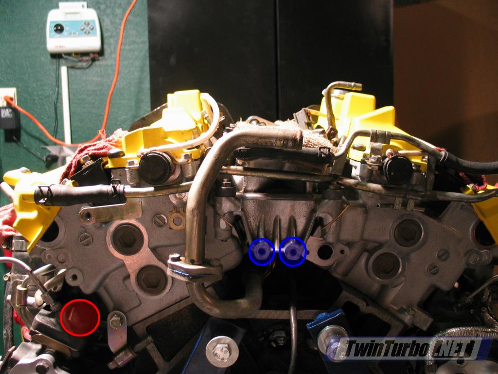
Step 38: EGR equipped vehicles: Install EGRSince my Z no longer has EGR, I have no pictures of this part.Reinstall the EGR valve on the back of the engine. Installation of EGRmay also interfere/coincide with the rear water line installations inthe next two steps, so modify the procedure as necessary.- Install the EGR valve assembly to the back of the block using two long 12mm bolts, noted in blue on (82.)
- Attach the exhaust line to the rear of the driver's side manifold, noted in red on (82.)
- The vacuum hose on top of the EGR will connect to a hardlineunder the plenum that ends up running to the EGR solenoid by thebattery. Remember to hook it up after the plenum is on.
| | Image 82. |
Step 39: Install rear upper water pipe (heater feed) and vacuum.Service Manual Reference: LC-9- Heater feed assembly is shown in (83.)
| | Image 83. |
- Apply blue Permatex to the water pipe fitting and secure with 2 10mm bolts. Green in (84.)
- Attach vacuum hose the driver's side rear valve cover vent pipe and attach clamp. Blue in (84.)
- Bolt the upper bracket to the small bracket on the passenger side VTC solenoid. Red in (84.)
| | Image 84. |
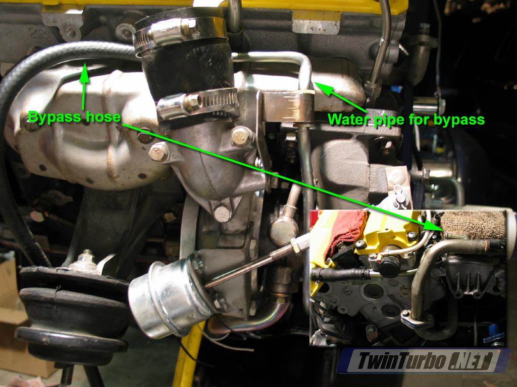
- In my case, I have done the throttle body bypass, so water hosescan be connected from the turbos to the rear water pipes. (NOTE: needto put note in about when to attach water hoses for non-bypassedsystems) On the driver's side, attach the upper water tube on the turboto the upper outlet on the rear water pipe, noted as bypass hose in (85.)
| | Image 85. |
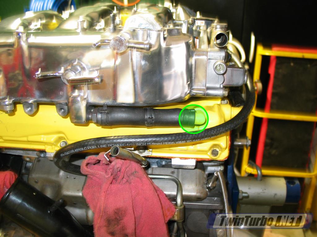
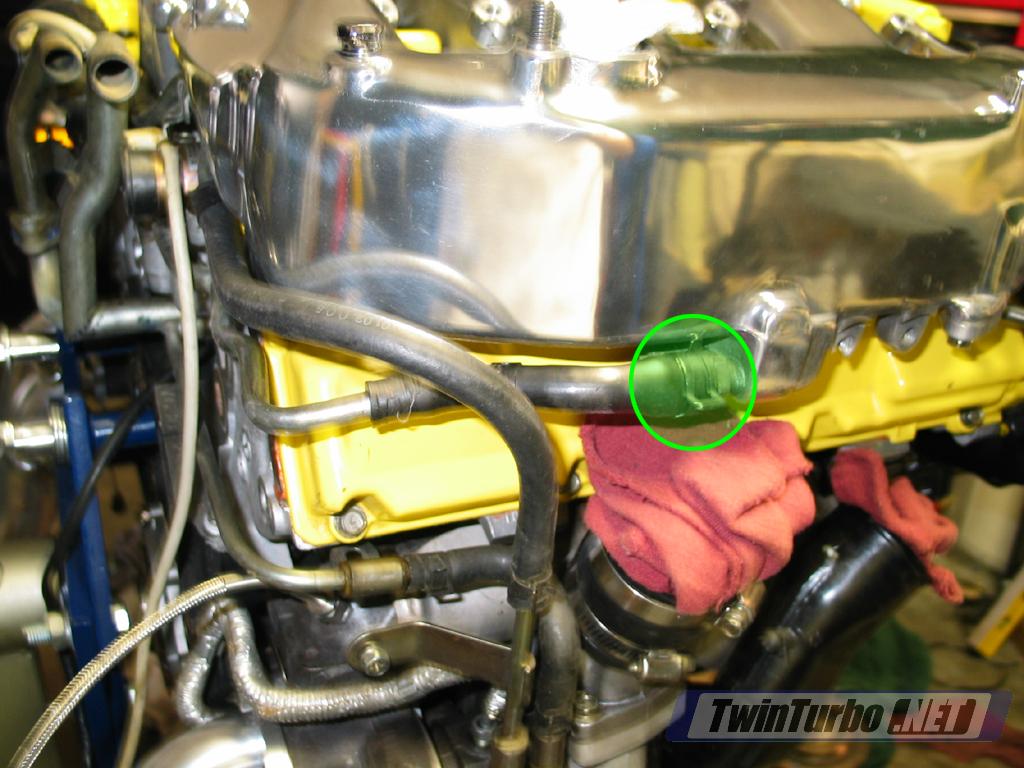
- Attach the rightmost upper pipe hose to the taller water pipe (rear) on the passenger turbo. Green circles in (86.)
| | Image 86. |
Step 40: Install rear lower water pipe (heater return)Service Manual Reference: LC-9- Heater return assembly shown in (87.)
| | Image 87. |
- Put a ring of blue permatex around the mating surface and attach to the block. Green circle in (88.)
- Attach hose on driver's side to the driver's side turbo lower water pipe using clamp. Yellow circle in (88.)
- Attach hose on passenger side to the passenger side shorter (front) water pipe using clamp. Blue circle in (88.)
- Attach bracket to upper hose w/ 12 mm bolt. Red circle in (88.)
| | Image 88. |
Step 41: Install power steering mount to passenger side head- Attach with 4 12mm bolts. Tighten down to 12-15 ft.lbs. (1.6-2.1 kg-m). Green circles in (89.)
| | Image 89. |
Step 42: Install upper intake (plenum)Service Manual Reference: EM-8- install new paper gasket from gasket kit. (90.)
| | Image 90. |
- Make sure VTC solenoid harnesses are clear and drop the plenum inplace. If you have EGR valve in place make sure the holes in the sidesof the plenum line up with the EGR intake tubes and slide into place.
- Hook up driver's side PCV valve hose and clamp in place. (91.)
| | Image 91. |
- Hook up passenger side PCV valve hose and clamp in place. (92.)
| | Image 92. |
- Install 8 12mm bolts for plenum. The short bolt goes in the front passenger side. Blue circle in (93.).The stud bolt goes in the 3rd hole from the front on the passenger side(stud is to attach the throttle cable cover to). Green circle in (93.)
- Torque all bolts to 12-15 ft. lbs. (1.6-2.1 kg-m). The servicemanual does not show a torque pattern, but I generally go in acriss-cross.
| | Image 93. |
Step 43: Install spark plugs- Install all 6 spark plugs into the heads. Be careful not to cross-thread the plugs when getting them started.
| |
|
Step 44: Install coil packs- Install 6 coil packs into the heads with 2 12mm bolts per pack and Tighten down. (94.) shows packs installed.
| | Image 94. |