|
This DIY is for a 2001 Camry XLE, 1MZ-FE, 6-cyl with 99,700 miles on the clock. I bought this car January of last year with 88,000 miles on it, and no service history. There was no sticker on the timing belt cover to say whether or not the timing belt was ever changed, so I'm assuming it wasn't and with the mileage approaching 100,000 miles it's time it was changed. There are several ways you could proceed. If you don't plan on keeping the car for more than a couple of years, then you could get by with just changing the Timing Belt, the Power Steering Belt, and the A/c belt. If you have over 120,000 miles on the car, and/or plan on keeping the car for many years, as I intend to do, then the full service should be done as described in this DIY. The 2000 Camry I had before this one, I had the timing belt, A/C and P/S belts changed at 100,000 miles. Then at 180,000 I changed everything as in this DIY, drove it another 50,000 miles with no problems and sold it, and got this one. I don't have a service history so I don't know what if anything was changed, and if there was any service, I have no way of knowing what parts were used. So I decided I would do a complete service at 100,000 miles along with the Timing Belt, even though it's not 100% necessary. There are several kits that you can buy for this project. Rock Auto sells all the necessary parts, and there are several sellers on eBay that also offer kits. And you could always go to a dealer, or somebody that supplies dealer only parts like ToyotaPartZone. Many members here have use an eBay seller, AirCabinMan and have been satisfied. I took a look at AirCabinMan's offerings, and there were two kits offered for my car. One was an OEM kit, that most TN members purchased. He also offered a 100% Toyota OE parts kit. Both would work fine, and if you are on a budget go with the OEM version, all the parts are good quality, and you will save $70.00 over the Toyota parts OE version. I decided to go with the Toyota OE kit, since I'm planning on keeping my car for a long time, and Toyota parts are top quality, and I felt it was worth the extra money. The total cost of the kit from AirCabinMan was $332.82, shipped. I had to pay an additional 25.79 sales tax for the kit, since AirCabinMan is based in California, and so am I.  Here are the individual parts and part numbers that were shipped in the kit  True to his claims, the parts were all original Toyota Parts, packed in original Toyota bags. The parts arrived Priority Mail in a few days. So thumbs up to AirCabinMan, for truth in advertising, and prompt delivery. I picked up some Toyota Red Coolant since I would be draining the coolant to change out the water pump. I could have re-used it, figured it would be a good time to change it too. It's pretty expensive, at $37.00 a gallon, but my local Toyota Dealer has a 20% Sunday parts discount, so I ended up paying $29.72 for it, tax out the door, $31.95. I also picked up some Permatex water pump gasket sealer at Autozone, although with Toyota's water pump gasket, theoretically you don't need any gasket sealer, but I like to use a little bit anyway. BTW, this Permatex Water Pump gasket sealer is good stuff. I used some to seal up a plastic drip pan in my home heating condenser drip pan, and it worked great.  The total cost of all of the parts, including tax came to $395.00. A call to the local Toyota dealer said a Timing Belt/Water Pump/Power Steering and A/C belt would come to $900.00. An independent mechanic might charge $200 less that a dealer. But that didn't include new idlers or tensioner, which would have added an additional $200.00 to the total. So there is significant money to be saved by doing it yourself. More if you go with the OEM kit instead of the all original Toyota parts. I don't think it's a good idea to go with the cheapest parts you can find to do this job. If one of the cheap parts fail, you will have a lot of work to get to them, and I don't think it is worth it. If you get your parts from Rock Auto, ToyotaPartsZone, Gary aka Toyopartsman (TN Sponsor), AirCabinMan, or even your local Toyota dealer, you won't have to worry about the hassle of re-doing the job. Or worse, getting stranded because a cheap part made with Chineseium broke. This is a pretty involved DIY and will take 4-5 hours. The first time I did it, it took me twice that, spread over Saturday and Sunday. You will need the following tools: 3/8" or 1/2" drive metric socket set. Either one will work but having both is better. Set of metric combination wrenches, open and box end. Short length, 18"-24" of 8mm or 5/16" Inside Diameter (ID) tubing Jack Stands Floor Jack Large drain pan for the coolant Torque wrench Impact Wrench Inspection mirror A few specialty tools that will make the job easier. Not mandatory, but nice to have. Lisle 58430 Seal Puller, Lisle 38220 Cam Adjuster, and some way to hold the Crankshaft pulley while the nut is tightened. We call it "The Club". More on these tools later. Jack up the car from the center jack point at the front of the car, just a little, maybe 3-4 inches. This should give you enough room to get the drain pan under the car to catch the coolant. It's also better to keep the car somewhat level while draining the coolant, so don't jack it up too far since you will be taking the passenger side wheel off, and it's much easier to break the lug nuts free with the weight of the car resting on the tire. Drain the coolant from both the radiator, and the block. The radiator drain is located on the passenger side bottom of the radiator. There are two engine block drain plugs. One on the front, and one in the back. Place a large catch pan under the radiator drain plug. Don't loosen the radiator cap, or the cap on the coolant overflow tank, or remove the hose that goes to the coolant tank. The cooling system is sealed, so when you open the radiator drain plug you will siphon out the coolant in the overflow tank. Then you can remove it from the fender, and clean it without spilling coolant all over the place.  The radiator drain plug is a white plastic thumb screw located at the very bottom of the radiator on the passenger side. Turn it counter-clockwise a couple of turns until you hear the water dribbling out. There is a hole in the skid plate that lines up with the drain plug, so if you are careful the coolant will drain through the hole, and into the pan. The larger the catch pan the better. No matter how careful you are, some of the coolant will find it's way onto the frame, and drip all over the floor. If you unscrew the plastic drain plug too far, then you will have a flood of coolant all over the place. Lots of newspapers on the floor are a good way to minimize the mess. If you want to avoid this hassle next time, you can remove the skid plate, and attach a short piece of hose to the drain plug, so next time the coolant will come out of the hose. Makes things a bit easier next time. You can see the hose I attached to the drain plug in the inset in the right hand picture. The arrow on the inset points to the location of the drain plug. The left hand picture shows the location of the front engine drain plug.  Next attach a piece of 8mm ID tubing to the front engine block drain plug, and loosen up the 10mm brass nut a couple of turns. You can get the plastic tubing at Lowes or Home Depot, They sell it by the foot. You will only need a 18"-24" to drain the front and rear of the block. (5/16" ID is the same as 8mm). When the coolant stops coming out, screw the bolt back in. Remember it's brass, don't over tighten it and strip out the threads. Do the same thing to the drain plug on the back of the block. The rear block drain plug is kinda hard to get to, and it's not the end of the world if you don't drain the coolant from the rear block drain plug. You might want to save this step until you have the car jacked up and secured with jack stands. Once all the coolant is drained, close the plastic petcock on the radiator, and double check both the front and rear drain plugs on the engine block are closed. The coolant reservoir tends to get crud settling at the bottom and it's easier to clean out once it's empty. There is a small clip that holds the hose from the radiator cap. Squeeze the clip and remove the hose by the radiator cap. The coolant tank is held in place by a single bolt attached to the fender, and a tapered pin at the bottom of the tank that fits into a rubber grommet. Removing it also gives you a little more wiggle room where you will be working. While the coolant is draining you can remove the Torque Strut, or as it's more commonly know as the Dog Bone. The white arrows are pointing at two ground wires that need to be moved out of the way. You can either un-clip them at the connectors, or unscrew the one bolt that secures them to the fender. Then unbolt everything connected to the Dog Bone mount. Remove the bolts circled in green first, then the ones circled in pink. You are going to have lots of loose bolts during this project, so get some plastic bags, and put the parts and the bolts in bags as you remove them. Don't for a minute think you will remember where they all go. There are two long bolts that go through what Toyota calls the "No. 2 RH Engine Mounting Bracket" and once the long bolts are removed it will come right off. Set it aside. You can see this bracket towards the right hand side of the picture. It's the shiny aluminum machined part sticking out on the right side under all of the black metal dog bone brackets.  Loosen the lug nuts on the passenger side front wheel 1/4 turn. Just enough to break them loose. Then jack up the car, place jack stands under the frame rails, and remove the passenger side front wheel. Once the front wheel is removed there is an access panel that is held in place by two 10mm bolts. Remove them, and the access panel. I like to screw the bolts back where they came from for safe keeping. Set the access panel aside. Next, you will need to remove both the Air Conditioning and the Power Steering belt.  There are three bolts that hold the alternator in place. One is a pivot bolt, and the other is a bracket that positions the alternator. The third, adjusts the tension of the belt. Loosen the pivot bolt on the right a couple of turns and then remove the nut on the left, and you should then be able to swing the black bracket out of the way. If you can't swing it out of the way, then back off on the pivot bolt a couple of more turns until the bracket can be swung up to the 12:00 position. Or you can remove it if you wish.  The tension of the alternator belt is by a long bolt that attaches to a bracket and moves the alternator on the pivot bolt in an arc to adjust the tension. It's a machined block, one hole that the long bolt goes through, and another hole at right angles that bolts to the bracket. You will have to loosen the bolt that is 90 degrees to the bracket that holds the alternator. It's a PITA to get to. You will have better access if you remove the fuse bracket, directly in front of the alternator, held on by two 10mm bolts, and moving the fuse block assembly out of the way. Even then you will only get maybe one flat at a time using a ratchet. An air ratchet comes in mighty handy for un-loosening this bolt, let me tell you. But if you don't have an air ratchet, you will just have to do it one or two clicks at a time, counter-clockwise. Fortunately you just have to loosen it a bit, maybe two full turns to allow the alternator bolt to relax the tension on the belt. Now you can turn the long tension bolt counter-clockwise to relax the tension on the alternator belt. When the belt is loose enough, remove it.  Back to the floor, to remove the Power Steering belt. There is a pivot bolt at the top of the pump that is very hard to see that holds the pump to the block. There is another one that is used to adjust the belt tension. It is located on the bottom of the pump. You don't need to worry about the bolt on the top of the pump, just loosen the bolt on the bottom of the pump. I like to remove it completely and then find some place to insert a pry bar under the power steering pump body, and rotate the entire pump counter-clockwise to relax the tension on the belt, so you can remove it. You will find that the pump will rotate only so far, and then it stops. If for some reason the belt tension is still too tight, you can just cut the belt since it will be replaced anyway, but whether or not you intend to keep or replace the belt, the power steering pump must still be rotated as shown to re-install the new/old belt.  Now for the hard part Remove the EFI fuse located in the main fuse block on the driver side fender. Be careful if you use pliers and don't squeeze the fuse too tight. It's thin plastic, and easily cracked. Just grab it and wiggle it back and forth while pulling up until it comes loose. The EFI fuse contacts are oriented in such a way so it only goes in one way, and can't be inserted the wrong way.  Get a long 24" breaker bar and a 22mm 6-point socket, preferably an impact socket, and wedge it against the floor as shown in the picture.  Then get in the car, engage the emergency brake, make sure the transmission is in Park, put your foot firmly on the brake pedal, insert the key in the ignition, but DO NOT ATTEMPT TO START THE CAR. Just blip the key to engage the starter. Turn the key until you hear the starter engage, and then release it immediately. Go check the breaker bar to see if the nut has come loose. If it hasn't then repeat the process. click/check, click/check until the bolt is loose. Here's a video of how it works. http://www.youtube.com/watch?feature...&v=2Zu5g95gpqo The crankshaft bolt is installed at the factory with some blue loctite and it leave some residue on the bolt. Use a wire brush to remove this crud.  Next you will need to remove the crankshaft pulley. Every time I've done this procedure, I've been able to just remove the pulley with my bare hands. I've read of members here on TN having a tough time removing the pulley. Well, now it's my turn. There are some things that you need to pay attention to, because if you don't it could cost you money, to the tune of $300. If the crankshaft pulley doesn't come off easily you will have to use some sort of wheel puller. There are several on the market to choose from, but there is only one type that you should use. The one shown on the left is what you will need. You might be tempted to use the one on the right, but be aware that it grips the pulley on the outer perimeter of the pulley where the belt grooves are the thinnest, and depending on how tight the pulley is stuck to the crankshaft, it could chip the pulley, and they aren't cheap to replace. So save yourself some major grief and get the right wheel puller. Harbor Freight has them for under $20.00.  Now you just have to screw a couple of bolts into the crankshaft pulley and remove it, right? Well, not exactly. Some Toyota engineer decided that it would be a good idea to drill and tap 7mm x 1.00 threads into the aluminum crankshaft pulley to mount the wheel puller. Small fine threads into an aluminum pulley. (?) I rummaged around and couldn't locate any 7mm bolts. Come to think of it, I can't remember ever using a 7mm bolt. No matter, I have a metric tap and die set, so I'll just re-thread a bolt that I already have. From earlier, you might remember that 8mm = 5/16" so using my calibrated eyeball I got a 2" 5/16 bolt and re-threaded it to 7mm x 1.00 and inserted it into the puller, and tried to thread it into the crankshaft. Well, it was too short so I abandoned my calibrated eyeball method and went and found a ruler. Then re-threaded a longer bolt, and threaded it into the crankshaft pulley, no problem. I tightened down on the center bolt of the puller, and it turned and turned and then with a loud clank the puller fell to the ground. The crankshaft pulley was on so tight that it stripped out the threads in the crankshaft pulley. FML. Now what? Well I'll tell you what. I did what they should have done in the first place. I re-threaded the pulley with a 5/16 x 18 course thread tap and ran some 5/16 x 18 bolts in the pulley and pulled it off, no problem. The crankshaft pulley was stuck on the shaft so tight, it wouldn't come loose, until the pulley was almost completely removed. What a PITA that was.  If this happens to you and you have to re-tap the crankshaft pulley while it is still installed, be very careful not to run the tap too far into the pulley, no more than 25mm or one inch. The lower timing belt cover is located right behind the crankshaft pulley, so be careful not to run the tap into the lower cover. You don't need to drill out the hole to accept the 5/16 x 18 tap. The 7mm hole is just the right size for the 5/16 tap. Of course you can use an 8mm metric tap, but I didn't have any metric bolts that were long enough. With the crankshaft pulley off now you can see the rubber seal between the inner/outer ring of the crankshaft pulley. It's very thin, and if you use a chain or strap wrench to hold the pulley, it's very easy to see how the inner and outer rings could rotate, and shear the rubber bond between them. If that happens, the crankshaft pulley is ruined, and will need to be replaced. Many people have reported using strap or chain wrenches with no problems, but I wouldn't recommend it.  With the Crankshaft dampener off you can see the lower timing belt cover. It is held on by 4-10mm bolts. Remove them and the lower cover will come right off. Bag the bolts and set them aside along with the lower timing belt cover. 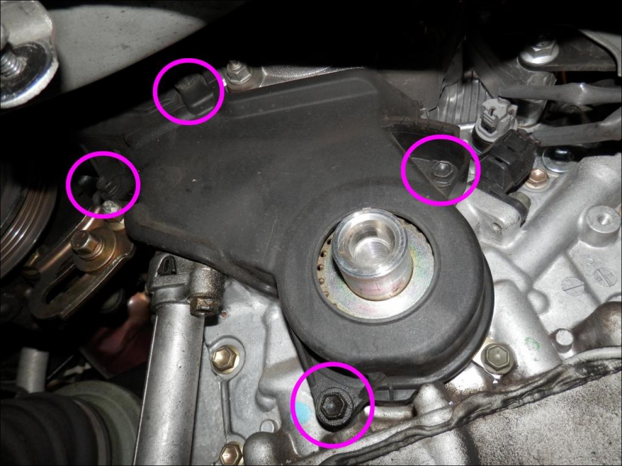 With the lower timing belt cover removed, the next step is to remove the Timing Belt Guide. It's cup shaped, and I've marked it so I get back in the proper orientation. If you forget to mark it, the concave side faces the engine block. It has a keyway machined in it, and you can just barely see it at the top of the picture, in the 11:00 position. Slide the Timing Belt Guide off the crankshaft and set it aside. Next loosen the 10mm bolt that holds the Timing Belt Plate. Loosen the bolt enough to rotate the plate, 90 degrees or so and then cinch the bolt down finger tight just to keep the plate held in position. You can remove it if you want, but it's easy to misplace, and overlook when re-assembling everything.  Next, remove the upper timing belt cover. You have to remove the lower one first because it overlaps the top one from underneath. The upper timing belt cover is held on with 5 bolts. Remove all of the bolts and bag them aside with the upper timing belt cover. It's hard to get a shot of where the bolts are located while everything is in the car. So here's a shot of both of the timing belt covers when they were removed to give you a better idea of where the bolt locations are. All of the bolts that hold the timing belt covers, both upper and lower are all the same, 10mm shoulder bolts. No need to mark where each one goes, but be sure to bag them.  One problem you will run into when trying to remove, as well as re-installing the upper timing belt cover, is that the timing belt cover closest to the firewall won't come out easily. The power steering hose is in the way. There are a couple of ways to get around this. The first is to drain the power steering fluid by sucking it out with a turkey baster, and remove the hose from the reservoir and then move it out of the way. Have lots of rags handy because no matter how careful you are, there will be some oil leaking out. You can just remove the one hose pointed out in the picture, or both. The one that the arrow points to, is the one you need to move out of the way. The other hose can stay attached to the reservoir, or you can remove them both, and remove the power steering reservoir. Another way is to just pull up on the power steering reservoir and detach it from the fender. It's held in place by a tapered flange, so if you pull up on it, it will come right off. Then you can push the hose towards the firewall with the hoses still connected, and with some fiddling, you will get enough clearance to remove the back part of the timing belt cover. Try this way first, and if you get enough room to remove the timing belt cover. If not, then remove both hoses, and the power steering reservoir for the best access. Neither hose is under pressure, so there is not danger of power steering fluid squirting all over the place. It just drips all over the place.  Once the upper timing belt cover is removed the next step is to remove what Toyota calls the "RH Engine Mounting Bracket". It is held on by two bolts and two nuts. Removing the bolts is easy, removing the nuts is easy. Removing the bracket is not. When you attempt to slide it off the studs, it hits the fender. The studs have a small star fitting on the end of them, and you might try to remove them, but will probably just round over the star fitting. They used blue locktite when they put the studs in at the factory, and they are in there very tight. You can also get a pair of locking vice grips, and try to unscrew the studs, but you will probably destroy the threads in the process. Or you can just hack saw them off and then remove the left over's with some vice grips. The studs are a dealer item, and if you plan on using the destructive method, be sure to get the new studs before you begin. But there is another way, but it has some real dangers associated with it. You can jack up the engine just a little bit, and then you can slide the bracket off the studs. It doesn't have to be much, just an inch or two. It's not easy to find someplace to position the jack, and the most obvious is to put a 2x4 on the jack, and lift the engine from under the oil pan. You are *not* supposed to do this because if you poke a hole in the oil pan, you are in for a lot of grief. Not only are the bottom oil pans expensive, they are a royal PITA to get to. So you have been warned. If you decide to jack up the motor under the oil pan, at least get a large piece of at least 3/4" thick plywood to spread out the force. Even then, you risk damaging the oil pan. Knowing all of this, and being extra careful, and using a large piece of wood, I ended up with a small crease in the oil pan. Fortunately it is only minor and doesn't leak. On a more positive note, with the engine raised, the bracket did come off easily without any damage to the studs. When I had tried jacking up the motor from the oil pan in the past, I had no problems. With the Dog Bone removed, the motor jacked up easily. This time however, it was much more difficult, and I think I know the reason why. All of the other times I used this method, the cars had much greater mileage than this one has. All were 180,000+ miles. So I'm just guessing that the front motor mount in those high mileage engines was shot, and offered no resistance to the upward pressure of the jack. Seems like the front motor mount in this car is in good shape, and was probably the cause of the greater resistance. Next time I do this, I'll remove the bolt that attaches the front motor mount to the engine, and see if that makes a difference. The only drawback to that, is that the oil filter is in the way, and would have to be removed to get to the bolt on the motor mount.  Here's what the bracket looks like when it's attached, and then when it's removed.  Now you can remove the studs. Using vice grips here is fine, because there is plenty of shank on the studs to grab, and any marks left by the vice grip jaws can be easily filed off once the studs are removed. You might try pliers, but I'm pretty sure that won't work. The studs are in there pretty tight. Another way is to get a set of these stud pullers. The set costs $40.00 and is great for removing and installing studs like this. It's a good addition to your tool box, and will last a lifetime. Inside what looks like a spark plug wrench, are metal fingers that grab the stud on the body and you rotate the tool. Then a socket or wrench on the end removes the stud cleanly without any damage.  Normally you don't have to change the Crankshaft/Camshaft seals. The seals keep out any oil that gets past the camshaft bearings from getting onto the timing belt. Chances are, the seals will be fine, and don't need to be replaced. The kit I bought had them included so I figured I'd go ahead and replace them. The main reason was that I got a Lisle 58430 Seal Puller and everybody said it was the best thing since sliced bread, so I wanted to see if it made the job easier. It's not very expensive, under $20.00 so I figured I give it a try. Before you can get to the seals, you have to remove the camshaft pulleys and the inner timing belt cover. It's not a lot of extra work and the advantage is that with the inner timing belt cover out of the way, the water pump comes off, and goes back on much easier. But it's not necessary to remove it to access the water pump, just makes things a little easier. The bolts that hold the Camshaft pulleys can be stuck pretty tight. Every time I've tried to remove them, they have come off without too much fuss. But some people have had a really hard time getting them loose. Leaving the timing belt fully tensioned, and connected to the rotating engine parts will offer substantial resistance to turning. With the belt off and the camshaft free wheeling, it's much more difficult. Toyota has a special tool to hold the Camshaft pulley, Lisle makes one, it called a 38220 Cam Adjuster, and I have one, but to be honest, it just isn't up to the task of holding the pulley very well. It's great for rotating the camshaft, but not so good to hold it under a lot of pressure. Toyota makes a Special Service Tool to hold the pulley, and it looks like it will work much better than the Lisle 38220 Cam Adjuster. All you want to do is to crack the bolts loose, you don't want to remove them. The Camshaft pulleys are keyed so there is not danger of them slipping if they are a bit loose. Using what I call the "Batter-up" method. First get the correct socket, 6 point if you have one. Then attach a long breaker bar to the socket and place it on the front right hand nut with the breaker bar at the 11:00 position. The closer you can get it to 12:00 the better. Then take a heavy piece of metal, I used a piece of 1/2" thick x 2" wide piece of flat bar. You can use a hammer, but it's harder to hit the breaker bar dead nuts with a hammer. The heavier the piece of metal the better. Then stand alongside the car parallel to the fender. And wind up with the heavy piece of metal and take a swing at the breaker bar as if you were trying to hit it out of the ball park. Usually one hit is enough to break the bolt loose. To get the back one off do the same thing, but you might have to get a little bit more leverage, and I did with another piece of pipe on the breaker bar. "Batter Up" and one swing later, and the bolt was loose on the back Camshaft. Now just cinch both of the bolts a little tighter than finger tight to keep everything aligned. And it's time to get everything lined up and to remove the timing belt. I know it sounds goofy, but with the rotating mass of the engine offering resistance and the sharp whack with a heavy bar on a long lever, has worked for me every time. Of course if you have a really big dick impact wrench, it will come off no problem.  Another method is to attach a socket to the bolts that hold the inner timing belt cover and wedge it between the webs of the camshaft pulley. Sounds like it should work, in theory it should work, but when Pmesfun tired it, and snapped the head of the bolt right off, and then he had to drill it out. Big PITA, so I wouldn't try that method. From Pmesfun's epic thread: Before the timing belt can be removed the engine must be rotated to a specific position. Re-install the large crankshaft bolt without the dampener pulley. Then rotate the engine clockwise until the marks on the camshafts line up, and the marks on the crankshaft lines up. This can be a bit confusing, but once you know what to look for, it's not all that difficult. There are two marks both at the 12:00 position on the inner timing belt covers, that need to be matched to the marks on both of the camshaft pulleys. I've marked them so you can see how they should be positioned. I recommend marking both the covers and the camshaft gears with some sort of highlighter because it will make re-assembling everything much easier. It's very difficult to see the timing belt marks on the camshaft nearest the firewall when you are trying to re-install the timing belt. Note the orientation of the camshaft pulleys. There is a lip on each of them. The one on the right goes towards the engine block, the one on the left faces out. Note: the timing belt needs to be installed to line up the marks. It's a bit hard to get a shot of the timing belt marks while the inner timing belt cover is installed on the motor, so I thought it might be helpful show the timing marks orientation this way. But at this point in the DIY these timing belt covers, and the camshaft sprockets have not yet been removed.  There are two marks that need to be aligned on the Crankshaft. There is a dimple on the Crankshaft Timing Gear that needs to be aligned with a casting on the block. The picture on the left doesn't show it clearly, but luckily I found a 6-cyl at Pick-n-pull and was able to get a good clear shot of the timing mark on the Crankshaft Timing Gear, and the dimple on the block. It's the picture on the right. If you haven't already done it, re-install the crankshaft bolt, and bar the engine over by hand, clockwise, until the mark on the crankshaft timing gear lines up with the casting on the block as shown. Then go up top, take a look at the marks on the Camshaft Sprockets. If they aren't exactly lined up at the 12:00 position as shown, rotate the crankshaft one more turn, clockwise. The camshaft sprockets marks should then line up with the marks on the inner timing belt covers and the marks on the Crankshaft should also line up. 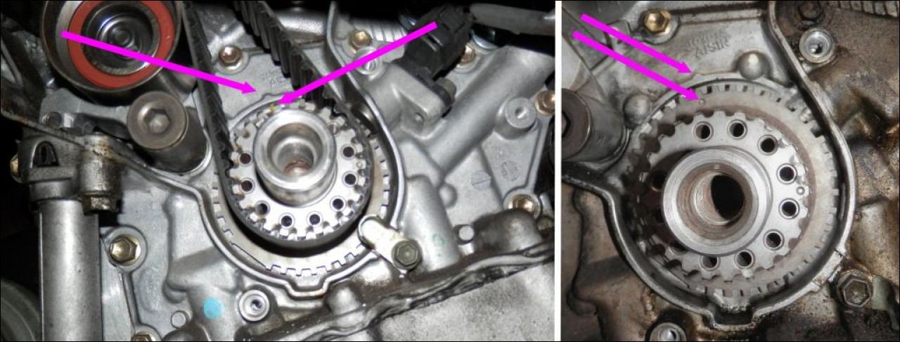 When all the marks line up, you can remove the timing belt, but first you must relax the tension on the timing belt. This is controlled by the hydraulic tensioner, and it is held in place by two bolts. Remove them, a couple turns each, alternating back and forth, until the tensioner comes loose, then remove the tensioner, and the timing belt. Note: If you haven't already cracked the camshaft sprocket bolts loose, now would be a good time to do it. See full description of how and why above. 
2001 Camry XLE V6 1MZFE
Submitted by xxx@******.com Revision 1 Article submitted on 20 Dec 2014 Last modified on 20 Dec 2014 Viewed 4112 times |
|
|
||||