|
Continued from Part I Once the timing belt is removed you can remove the camshaft sprockets. From earlier if you used the "Batter Up" method, or some other method to loosen the bolts then you can unscrew the bolts and remove both of the camshaft sprockets. You might need some way to hold the sprockets while you unloosen the bolts. There are a couple of ways you can do this. One is to lay the timing belt over the sprocket, and clamp it using a large C-clamp, large channel locks, or woodworkers clamp. The camshaft sprockets could be gouged and distorted, so go easy with the clamping. The bolts should come out easily if you broke them loose as described earlier. If you forgot to do it early on, it would be best to leave the timing belt in place and use the engine's mass as resistance to break the bolts free. Here's some examples of the right way, and the wrong way to hold the camshaft sprocket. The pics on the right is the wrong way because the clamps are directly on the camshaft sprocket, the pics on the left show the correct way because the clamps use the timing belt as a cushion. 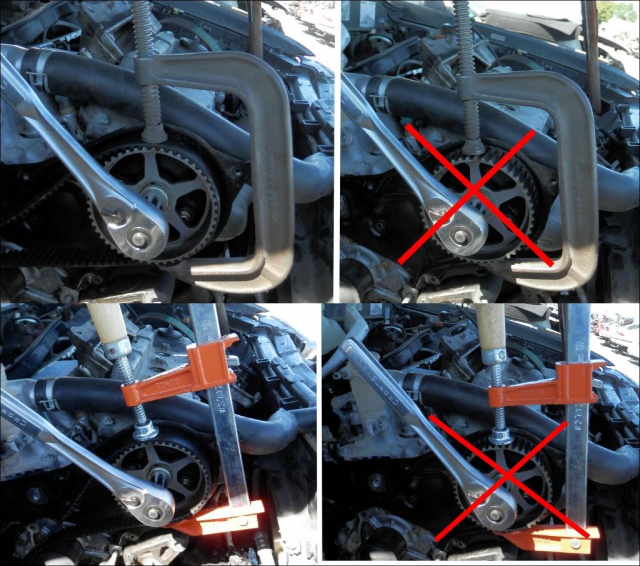 Another way to hold the camshaft sprocket is with a Lisle 38220 Cam Adjuster. It uses the inside webs of the camshaft sprocket, so it doesn't matter one way or the other whether the timing belt is left on or not. This tool comes in very handy for rotating the camshaft sprockets to get the alignment marks lined up on the timing belt. It's also handy for applying resistance when fastening the bolts. But it doesn't work all that well when trying to loosen really stuck bolts. It tends to wiggle around and ends up at goofy angles when you really apply a lot of torque to both it and a breaker bar. But it's still a great tool to have.  There is a wiring harness that runs across the top of the inner timing belt cover. There are 4 places where it attaches to the top of the cover. Insert a small screwdriver in the slots on the clips while pulling up gently on the wiring harness. Push it out of the way when all of the clips have been released. You can see the clip locations a few images back. Next remove the upper idler, it is held in place by one bolt. The lower idler is held in place by a 10mm allen hex head bolt. Then remove the six 10mm bolts that hold the inner timing belt cover in place. It comes from the factory with a sticky goo gasket material but it should come loose easily. Remove it and set it aside.  One of the advantages of removing the inner timing belt cover is much easier access to removing and replacing the water pump. It isn't 100% necessary but it makes it a whole lot easier. Here's a close up shot of the inner timing belt cover overlapping the water pump. If you watched the Scotty Kilmer video on YouTube you will see him struggle to get the water pump back in place. With the inner timing belt removed it's a piece of cake.  Here's a shot of the back side of the inner timing belt cover after it was cleaned up. You can see the sticky goo gasket material better here. When you get the inner timing belt cover off, take a look at the side that mates with the camshaft closest to the firewall. Depending on your luck you might see nothing, but more than likely it will be covered in oily dusty gunk. This is because of the orientation of the motor. It's tilted on a 30 degree angle, and unfortunately every one of the 6-cyl motors ever made will leak from the valve cover gasket closest to the firewall. This is called Bank 1, FWIW. I was lucky and there wasn't too much gunk to clean up because the first thing I did when I got the car at 87,000 miles was to change out both of the valve cover gaskets. So if it's a mess back there, clean it up as best as you can, and face the fact that changing the camshaft seal, will help, but not stop the leak in the future. You will have to remove the rear valve cover, and change out the valve cover gasket, which unfortunately is a PITA, and will probably take a minimum of four hours to accomplish.  With the inner timing belt cover off you can remove the water pump. It is held on by 4 bolts circled in pink, and two nuts circled in green. To keep things straight I got a piece of cardboard, put the new water pump face down on the cardboard, and then traced the outline of the water pump. I marked the holes where the studs and the bolts went as well as the nuts. As I removed each of them from the old water pump, I just poked them into their corresponding holes, and that way there is no chance of mixing the bolts up. I also marked the old water pump as to where the studs went that held on the Dog Bone Bracket mount. You can see the mark on the hole, top right. The other stud goes bottom left, but it's hidden by the water pump pulley. The other two holes, top left, bottom right, are where the long bolts go. If you forgot to mark them, it's a good time to do it on the new water pump before you install it so as not to mix up the placement of the studs and the bolts. In the lower left hand corner you can see some of the coolant in the water pump cavity. Because I didn't bother to drain the back engine block drain, there was still some coolant in the block, and it dripped out when I removed the water pump. Not a lot, and it was easy to mop up with some newspapers and paper towels. You can see the stock water pump gasket left in place. One thing Toyota did right was the design of this gasket. It has a neoprene lip that seals very effectively, and although I bought some gasket sealer, I ended up not using it. But some water pump kits come with a paper or flat gasket without the neoprene rib, so in that case I would have used the gasket sealer. But as it turns out, it wasn't needed. 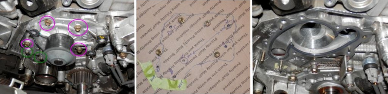 The inside of the water pump looked almost brand new, and could have easily gone another 90,000 miles until the next timing belt change. But the drive pulley had some crud from the timing belt, and I have no clue as to how it got there. I could probably been cleaned off, and it would be fine, but it really didn't matter since I was going to replace the water pump anyway.  Now for the hard part. I've never been able to remove the crankshaft or camshaft seals easily, or at least in a way I'd recommend to anybody. I saw a Lisle 58430 Seal Puller and thought it might be the answer to my problems. I picked one up and was looking for an easy removal of the seals. Sadly it didn't happen. When I tried to use the tool, it just tore out the seal. The lip was too small. Additionally the fulcrum was all wrong. The snout of both the camshaft and especially the crankshaft were much longer than the supplied piece of spring steel used to remove the seal. I tried everything I could think of, but had no success with the tool. So I went back to my old method of sticking a small screwdriver under the lip of the seal and prying it out. It works, but I'll be the first to admit it's pretty lame. First insert the flat blade of the screwdriver under the lip of the seal against the camshaft. Then pry the seal out a little, reverse the screwdriver to the other side, pry out a little, and go back and forth if necessary until the seal comes loose. Usually they pop right out. You can see in the picture on the far right a close-up of the marks left on the camshaft. They are minimal and can be polished out with some fine emery cloth and some oil. You can further minimize the marking if you put some tape on the side of the screwdriver that contacts the camshaft.  Another method is to drill a small hole in the edge of the seal and then insert a screw in the hole, and remove the seal that way. I've never been able to drill the hole as suggested. The drill always walked off the center punch mark, and ran into the camshaft and possibly gouging it. The other way is to use a self tapping drywall screw but I've never been able to make that work either. The problem lies in the construction of the seal, so I thought it might be a good idea to cut them open and see what the cross section really looks like. Once I did that it became clear what the problem was. Here's what the crankshaft and camshaft seals look like compared to one another. There is a small spring on both the seals that rests in a lip that keeps tension on the shaft.  With the seals cut open you can see what you are up against if you attempt to drill a hole in the seal. The camshaft has only a 3mm, or 1/8" lip that you need to center the drill into. It might be possible to drill the seal on camshaft nearest the radiator, but I never could figure out how to get a drill in position on the camshaft nearest the firewall. You could do it with a right-angle drill, but I don't have one of those. Drilling out the crankshaft seal presents another problem. Small drills aren't very long and you can see in this mockup the drill has to be at an angle to allow the drill chuck to clear the shaft. So if you're really careful, have a long small right angle drill, you should be able to drill a small hole in the seal and run a screw into it. I know it can be done, because I've seen pictures of people that have done it, but I could never get it to work as advertised. In the cross section you can see, what I thought was a spring, but turns out to be just ribs cast into the plastic part of the seal. If you look carefully you will be able to see the cavity for the spring as well as the spring poking out of the end of the seal.  Fortunately there was a 6-cyl Camry out at Pick-N-Pull for me to experiment on so I decided to try some different options without having to worry about destroying my engine internals. Using a drywall screw I attempted to remove both the camshaft seal and the crankshaft seal. You can see that it walked right off the metal part of the seal and wedged itself between the seal and the shaft. It could be removed with pliers but left a pretty bad marks on both the camshaft and crankshaft. I'm not sure that this could be removed with sandpaper or a file. Attempting to remove the seals this way would risk permanently damaging both the crankshaft, and camshaft, so there's no way I would ever risk using this method.   I'm sure Toyota has a special service tool to remove the seals without any damage, although I've never seen one. If I find a picture of one, I'll post it. And maybe come up with a home made version to try the next time. It would have to have arms at least 3" long to clear the crank snout and the lips would have to be at least 1/4" to be long enough to get under the lip of the seals where the Lisle tool wouldn't because it was too short. OK, moving right along....By now everything has been removed, cleaned up and it's time to start putting things back together. To replace the seals, you can get some 1-1/2" PVC tubing at Home Depot and make yourself a seal installation tool. Cut a piece of the PVC pipe 3" long, de-burr the edges. Apply a light film of oil or grease to the seals, and position the seals on the shaft, wiggle them with your fingers until they seat, and then tap them in place with the PVC pipe. You can use it for the camshaft seals as well as the crankshaft seal. The PCV works great because it won't damage the seals, or the metal shaft. Be sure to cut the edges square that will fit against the seals.  There are many nuts, bolts and they need to be torqued to the correct specifications. Here's a diagram of all the parts along with the torque specs. Note, the ft/lbs are the last number in the parentheses. 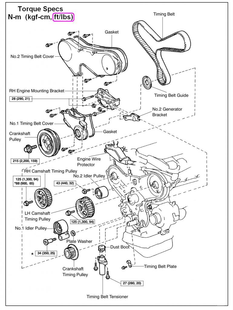 First up is the water pump. Make sure all of the water pump mating surfaces of the engine block are clean and dry. There are two guide pins that align the gasket, and it should slip easily over these pins as well as the two studs in the lower left hand corner. Then position the water pump on the studs, slide it in place and be sure it seats on the guide pins without binding. Once in place, replace the 4 bolts from the cardboard holder, add a little blue Locktite, and torque to specs. The inner timing belt cover can be installed next. It's pretty straight forward and fits into place easily. It should slip in and align with the bolt holes, and the camshafts. It should fit flush with the motor and be straight. Re-install the 6-10mm bolts with a little blue Locktite and torque to specs. Then install the upper idler. It is held in place with one shoulder bolt. Be sure that the shoulder part of the bolt fits inside the upper idler bearing. It flops around a bit, so start the bolt a few turns, then pull out on the idler bearing to center it in the shoulder, and then tighten the bolt. Give the idler a spin to be sure that it spins free, and is square to the block. add a little blue Locktite and torque the bolt to specs. Next install the lower idler bearing that acts as the tensioner. It also fits on a shoulder bolt and unlike the upper idler, it goes on only one way, and there is no chance of it not being properly seated. However, there is a washer that goes *behind* the lower idler bearing and it is a bit fiddly to get in place. This washer is easily mis-placed among all the parts, and don't make the mistake of installing it the wrong side of the idler. The bolt is tightened down with a 10mm hex head allen wrench, and a little blue Locktite. Note, do not install the tensioner yet.  There's a little more cleaning up to do. Once the water pump is installed, there should be no more coolant dripping on the front of the engine. Wipe up whatever is still there, and then focus your attention on the crankshaft timing gear sprocket. It's a good idea to remove it, so that you can clean up any crud stuck on the crankshaft. It should just slip right off, but if it doesn't there are two small holes that are tapped for bolts and a wheel puller. I think they are 6mm or 7mm threads, but I can't remember for sure. The FSM warns about scratching the gear, so treat it gently. The stepped blocks on the outer circumference are for the crankshaft timing sensor. You can see it at the 2:00 position. With the gear off, it's a good time to remove and clean the bottom of the sensor. It is held in place by one 10mm nut, but you might find it hard to fit a box end wrench in there. You can use an open end one, but risk rounding off the flats of the bolt. I had to grind a 10mm box end wrench so it would fit. But YMMV on whether you need to do this, depending on the wrenches you have. The sensor should slide right out, and on the bottom is just a can shaped piece of metal. Mine was covered in crud, black crud, that was very difficult to remove. To be honest, I don't know if cleaning this sensor is necessary, but I figured it couldn't hurt. Be careful, the wires are delicate, and the sensor is expensive. Once it is cleaned up, replace it, and bolt it back in place. Clean off the crankshaft of any coolant that may have dripped on it, and using some fine emery cloth, or steel wool and a little oil as a lubricant, remove any rust, or other crud that is stuck to the crankshaft. Then the crankshaft timing gear should easily slide back on the camshaft. The gear is keyed to the crankshaft, so it only goes on one way. Put some grease or anti-seize compound on the inside of the gear and the crankshaft to make removing it a bit easier next time. 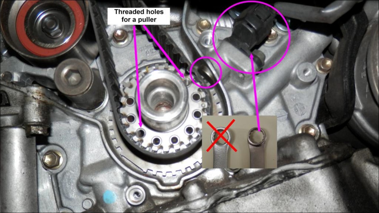 Now comes the tricky part. When you take the timing belt off, you might think to yourself, hmmm, this looks brand new, and doesn't need to be changed. Truth is, the timing belts rarely break but they do stretch, and that's the main reason to change the belt. As the belt stretches it alters the stock timing from where it should be. When I measured the old one against the stock Toyota belt, I found that it had stretched 1/2" which equates to a couple of teeth on the timing belt. I taped some twine to the outside of the old timing belt, and marked it. You can see by the overlap, that it had stretched when compared to the stock new one. As the belt stretches, the tensioner will not be able to apply the necessary tension, and that could lead to the belt skipping a tooth, or even a belt failure. Fortunately, these engines (without VVTI) are non-interference, and no damage to the engine will happen if the timing belt breaks. But a stretched belt, means poor performance.  The installation of the timing belt is pretty straight forward but there is lots of confusion regarding the marks on the belt, what goes where, etc. If you get a stock timing belt it should have three marks on it, and some printing by one of them. In the diagram below, you can see it at the bottom. The stock timing belt has arrows, and FR printed on the belt. This side of the belt goes on the right (towards the radiator) as shown. There are 211 teeth in the timing belt. From the bottom center mark, where the printing is, there are 75 teeth on the left side, and 77 on the right side, and 59 teeth between the top two marks. Actual spec length of the timing belt is 66 1/2" but I measured the outside circumference of the stock Toyota belt to be 67 5/8"-67 3/4" and the difference might be due to the radius of the spec measurement.  The confusion comes in where to position the bottom mark on the timing belt. If you remember back when you positioned the engine before you removed the timing belt. You positioned the marks on the camshaft gears with the marks on the inner timing belt cover. And you positioned the crankshaft pulley to the dimple cast on the block. Now when you install the timing belt, you position the top two marks with the marks on the camshafts, but the bottom mark is lined up, *not* with the dimple at the 12:00 position on the crankshaft sensor, but at the 4:00 position on the camshaft gear itself. A picture shows it better. It's also a good idea to use some sort of clamp to hold the belt in position once you get the marks lined up. 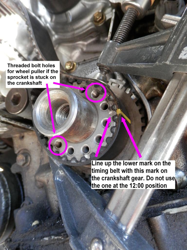 The FSM shows this as the order to install the timing belt. You can do it this way, but you might run into some trouble getting the belt marks to line up with the camshaft sprocket closest to the firewall. Almost certainly that camshaft has rotated off the marks. It's almost impossible to tighten the bolt and not have it move, 90 degrees to the left or right. This is where the Lisle Cam Adjuster pays for itself. If you are lucky and the camshaft rotated counter-clockwise then you can use a wrench on the bolt to get it back into position. But if it rotated clockwise, trying to turn it back into position will likely just loosen the bolt and you will be stuck.  You can make your own tool out of a piece of flat bar stock, maybe 12" long, 1" wide with a couple of holes drilled in it and some nuts and bolts will give you a working copy of the Lisle Tool. Something like this.  One thing I'm not sure about is that if you can rotate the camshaft a full turn clockwise and not get the engine out of time. I've never done it, and I don't know if it would work. Maybe somebody that knows for sure whether the camshafts can be rotated clockwise 180 degrees without affecting the timing. Comments are welcome. However you do it, you must line up the marks as shown. You can follow the factory procedure, but you might also find that it is very difficult to see and align the camshaft timing marks on the camshaft nearest the firewall. You might try a couple of options. One would be to position the belt on the crankshaft, then the water pump, then the right hand camshaft (towards the radiator). Bypass the center idler, and align the marks on the left hand camshaft (towards the firewall), go around the bottom idler, and then come back and slip the belt on the top center idler. Another way is to do it backwards from the factory order. Start at the bottom with the crankshaft, then the tensioner idler, then the left hand camshaft. Clamp the belt on the left hand camshaft so it won't slip off, and continue threading the belt around the idler, right hand crankshaft, and then the water pump. Whatever method you chose you will need to verify that all of the marks are correctly aligned. The ones on the crankshaft, and the right hand camshaft are easy, and in plain sight. The left hand camshaft is very difficult to see whether it is correctly aligned. You will need some sort of inspection mirror to verify that the left hand camshaft is properly aligned. Here's what it looks like when it's lined up.  After everything is lined up, then install the new tensioner. It is held in place with two bolts. It only fits one way into the cavity in the block. The black rubber part faces out. The new tensioner comes with a pin installed. Don't remove it yet. Put the tensioner in place and tighten the nuts a few turns one bolt, then a few turns the other bolt. Go back and forth until the bolts are torqued to specs. Then pull the pin from the tensioner, and the you should see it push the idler up and put tension on the timing belt. Next install Timing Belt Guide and the Timing Belt Plate. The Timing Belt Guide is the gold colored flat washer that slips on the crankshaft, and the Timing Belt Plate is the small finger held in place by one bolt. If you didn't mark the Timing Belt Guide orientation, the concave, or dished/depressed side faces out. The domed side goes against the timing belt, like this:   You might be tempted to install the lower timing belt cover. But don't do it just yet. Next comes the Dog Bone mounting bracket, or as Toyota calls it, the Right Hand Engine Mounting Bracket. It's held in place by two long bolts, and two studs. There are a couple of ways to approach this. One way is to re-install the studs in the water pump and torque them to specs. Be sure to get them in the right spot. The studs go in the far right hand hole and the bottom left hand hole. Then place the long bolts in the mounting bracket and wiggle it onto the studs. Once in place you can cinch down the bolts, and tighten the nuts on the studs. You may have to jack up the motor to get the bracket to slide on. Be careful, see the warning above. Although I've never tried this, another way would be to put the studs loosely in the bracket, along with the long bolts and after the bracket is in position tighten the studs with the a female star socket if you haven't munged up the ends trying to get them off while the bracket was still in place. Seems ff you chased the threads in the block with a tap, this should work but I'm not sure how tight you could get the studs using just the star socket. It would save the hassle and the problems associated with jacking up the engine. Next time I'm going to try it and see how it goes. But this time, I just re-installed the studs with the stud puller socket, and jacked the motor up a bit, and slid the bracket in place and tightened down the nuts on the studs, and the long bolts. Once you double check that all the marks line up, you can put the upper timing belt cover back in place. You will have to wiggle it to get it into place over the left hand camshaft. It's much easier to do this with the Power Steering hose out of the way. Sight down between the upper timing belt cover and the fender. The spacing should be even, about 1" or so. If it's not even then find out where the upper timing belt cover is binding and correct it. If the upper timing belt cover is not installed correctly, you will know it when you start up the engine. The belt or camshaft sprocket will be grinding on some part of the cover. So take special care to see that it is installed correctly. It is held in place by five 10mm bolts. Don't put a bolt in the bottom hole at the 6:00 position on the upper timing belt cover. That one is held in place by a bolt from the lower timing belt cover which is next to be installed. Be sure to align the bolt holes in the bottom timing belt cover and the part that overlaps the upper timing belt cover. The lower timing belt cover is held in place by four bolts. The crankshaft dampner pulley is next. It is keyed and held on by one bolt. Apply some grease or anti-seize compound to the inside of the pulley and the crankshaft to make removing it the next time a bit easier. Align the keyway in the crankshaft and the pulley and slide the pulley onto the crankshaft. Then install the bolt and large flat washer and torque to 160 ft/lbs. Unfortunately when you attempt to tighten this bolt, the engine begins to turn at about 80 ft/lbs. So you have to come up with some way to hold the crankshaft pulley while you tighten the bolt. Toyota has a Special Service Tool to do this but there are alternatives. The cheapest way is to make yourself up...."A Club". One of the TN members, DZ63 made one for his epic 4-cyl timing belt thread, stickied at the top of the forum. What he made is first class, and I refer to DZ63 as the King of Clubs. Although I couldn't make one as nice as he did, I cobbled something together from parts I picked up at Home Depot's plumbing department. This attaches to the crankshaft dampner with two bolts and then the socket goes on the bolt. The Club is positioned in such a way that when you tighten the crankshaft bolt, it will rotate and come to rest against the frame of the car. Once lodged in place you can the torque the bolt to the correct specs. Then remove the club and save it for the next timing belt job.  If you don't have access to welding equipment, there are many other ways to approach making a club. There is a sticky posted at the top of the Gen 3/4 Forum that has many other TN members suggestions. Take a look at it, and come up with one of your own, and add it to the thread. If you decide to make your own Club then bolt it to the crankshaft, and position it to lock against the frame, and then using a torque wrench, you can tighten it to 160 ft./lbs.  Now you can install the power steering belt. Loop it around the power steering pulley first, and then along the top of the crankshaft pulley. If it doesn't slip on, you can bar the motor over while guiding the power steering belt along. Every time I've installed a power steering belt, I've had to force it on. But this is the first time I've installed a Toyota belt, and it slid right on without having to bar the motor over to get it on. Insert a crowbar or large screwdriver at the top of the power steering pump and locate a place on the frame to pry down to apply tension to the belt. When tensioned properly, tighten the adjustment bolt. Then install the Alternator belt. Loop it around the crankshaft pulley, then the Air Conditioner Pulley and then the alternator. Re-install the Alternator Bracket but do not tighten the bolts. Tighten the adjuster bolt at the front of the alternator until the belt is tensioned. Then tighten the adjusting lock bolt at right angles to the adjustment bolt. Then tighten the large alternator pivot bolt and the nut holding the alternator bracket.  Install the access cover with two 10mm bolts, and install the front passenger tire, and tighten the lug nuts. Remove the jack stands and the floor jack and torque the lug nuts to 76 ft/lbs. Next install the Torque Strut Bracket (aka Dog Bone). It is held in place by two long bolts that fasten to the No.2 RH Engine Mounting Bracket. Although there is a locating pin the bracket can still wiggle a bit. Position it so it is parallel to the upper timing belt cover and tighten the bolts. Do not torque to specs yet. Position the Torque Strut and install the one bolt that attaches to the fender. Do not torque this bolt yet. Install the RH Mounting Stay with 3 bolts. With all the bolts installed loosely wiggle the entire assembly until everything seats. Then tighten all the bolts to spec.  If you disconnected the power steering hose, re-connect it, and fill the power steering reservoir with the correct amount of ATF fluid. Re-connect the coolant bypass hose to the coolant reservoir. And if you haven't already done it, add the coolant. Remove the radiator cap, and pour in the gallon of the Toyota Pink concentrate. Then top it off with one gallon of distilled water or until it just barely overflows the radiator cap. Add the excess distilled water to the "Low Mark" on the coolant reservoir. Start up the engine and check for leaks, loud noises, or any other weirdness. I was really amazed at how quiet the motor was compared to before all the parts were changed. I mean the motor didn't sound like it was falling apart before the parts swap, but now it purred like a kitten. So it would seem that replacing the idlers and the water pump was a good idea. I'm glad I did everything at 100,000 miles. Tighten the radiator cap, and the cap on the coolant overflow tank and go for a drive. Don't stray too far from home. Just around the neighborhood. Have someone follow you if possible. Turn the heater up full blast on hot and drive around until the motor warms up. Pay close attention to the temperature gauge. If it starts getting close to the Hot mark, head back home. Otherwise keep driving around for 10 minutes or so. When you come back and park the car look at the level in the coolant overflow tank. If it is pink, then the coolant level in the car was OK because excess coolant in the radiator has bubbled out into the overflow tank. If the coolant level has dropped, then add some more distilled water. Monitor the coolant level for a couple of days until the coolant level turns pink, and stays between the low and full marks. You might hear some gurgling in the morning when you start up the car. If you hear this, it means that there is still air in the system. I've never had to burp the cooling system. It seems to sort itself out in a few days. But YMMV. Check under the car for any coolant leaks, and check the P/S and A/C belt for correct tension. If everything checks out OK, pat yourself on the back for a job well done and knowing you won't have to do this DIY again for at least another 90,000 miles. There were a lot of pictures and a lot of links and hopefully I got the images and the pics where they are supposed to be. Let me know if you see anything out of place.
2001 Camry XLE V6 1MZFE
Submitted by xxx@******.com Revision 0 Article submitted on 20 Dec 2014 Viewed 6380 times |
|
|
||||