|
Modification Type: Performance Difficulty of Install/Modification: Moderate Preparation And Install Time: 5 hrs This clutch installation article is aimed for the 4AFE and 7AFE engines (Celica ST). The 5SFE (Celica GT) and FWD cars that have the 3SGTE swapped in can use this article as a good guideline. When it comes to changing the clutch for the 5SFE or the 3S-GTE, the only difference is the location of the starter. Everything else is very similar. When it comes to changing the clutch, there are five main things we need to remove:
Stuff you'll need:
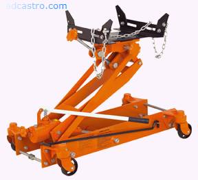
So yes...if you can, please try to get this. It will definitely make your clutch install 10 times more fun. Figure 1 (courtesy of harborfrieght.com)
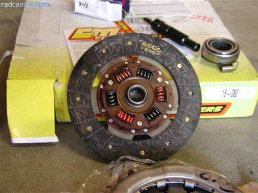
And so we begin by showing you some shots of the clutch we're going to install. Figure 2 (this is a stage 1 clutch. It's a bit better than OEM but not completely performance)
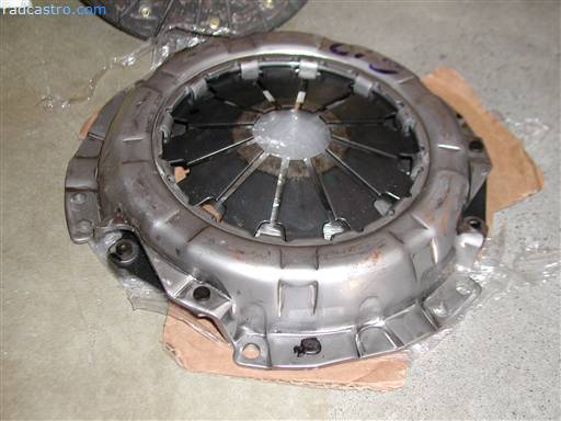
Figure 3 (clutch cover)
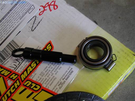
Figure 4 (alignment tool and throw bearing)
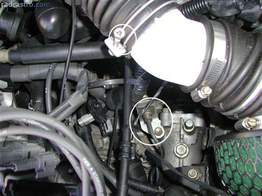
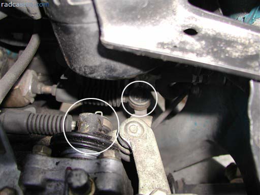
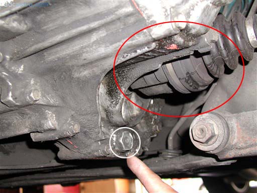
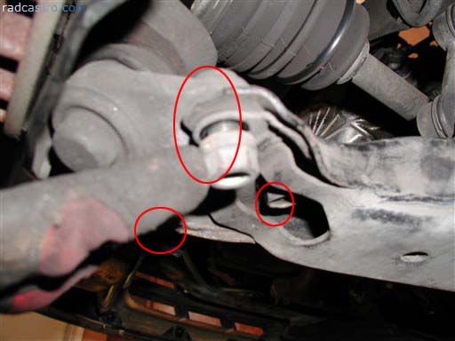
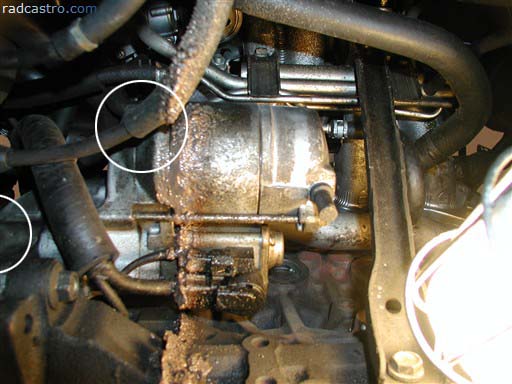
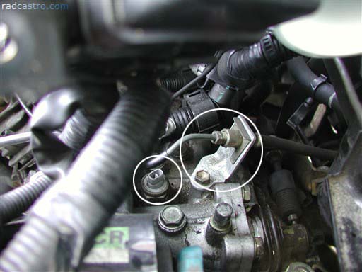
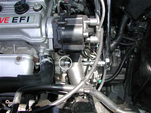
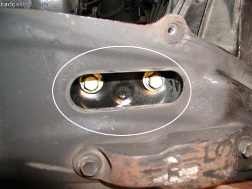
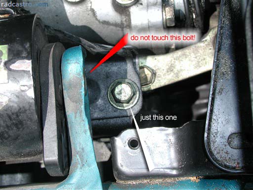
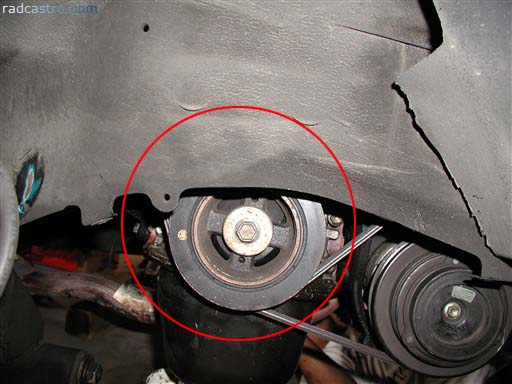
Now that we're done looking at the clutch goodies. Let's get back to work. The first thing we need to do is disconnect the battery and remove the air intake pipes. If you have a short ram intake like the one below. There will be less work. For everyone else, expect to deal with the cumbersome air box. On another note on Figure 5, you'll see that the bigger oval/circle is a bolt attached to some hydrolic line. That hydrolic line is responsible for engaging your clutch. Remove it? Yes. Figure 5
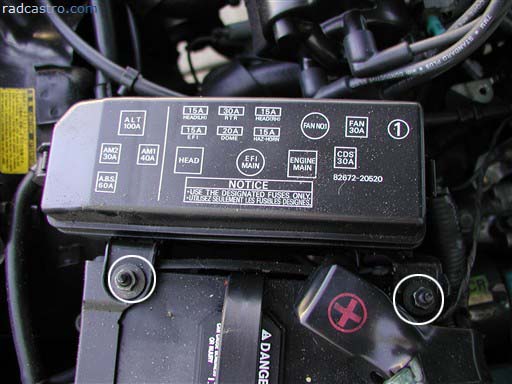
Detach the fuse box from the battery for more room. Figure 6
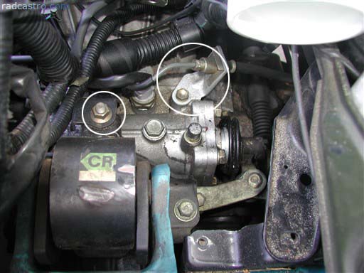
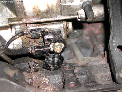
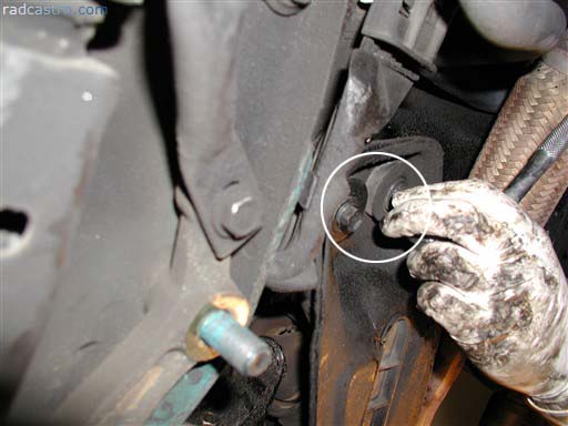
Remove this bolt and the hydrolic line if you haven't already. Figure 7
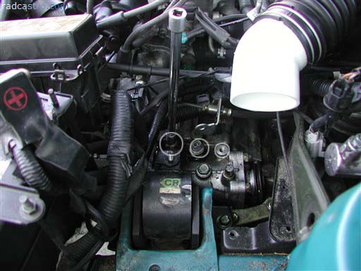
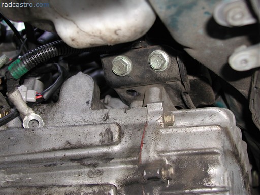
Unbolt the transmission sensor from the transaxle (the formal name for transmission) Figure 8
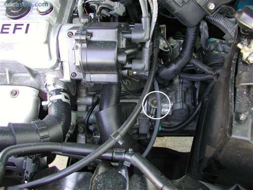
There are things that can be removed from the top of the transaxle so if you know what you're doing, go ahead and remove the simple stuff. Otherwise, consider yourself new to this and you can go through the rest of this artcle and follow the intructions step-by-step. Here are the shift cables/linkers that connect to your shift lever. Remove the hitch pins. Oh and make sure you have a new pair of hitch pins lying around. You can still reuse the old ones but they tend to bend. Figure 9
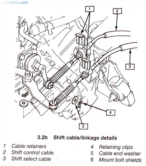
From this point, we can remove the clip so that the lines are free from the transmission. Diagram below is courtesy of Chilton's manual for Celica 89-93 (used with permission) Figure 10
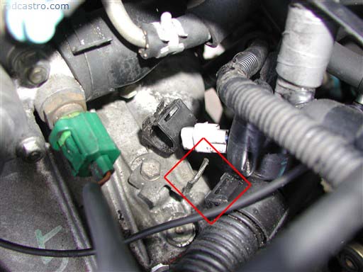
Unclip other things that may stick to the transaxle like this wire thing. Figure 11
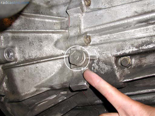
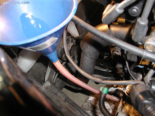
Jack the car up and remove the car's undercovers. This thing I'm pointing to is the bolt to fill the transaxle with gear oil. We will unbolt this now. Figure 12
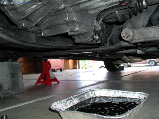
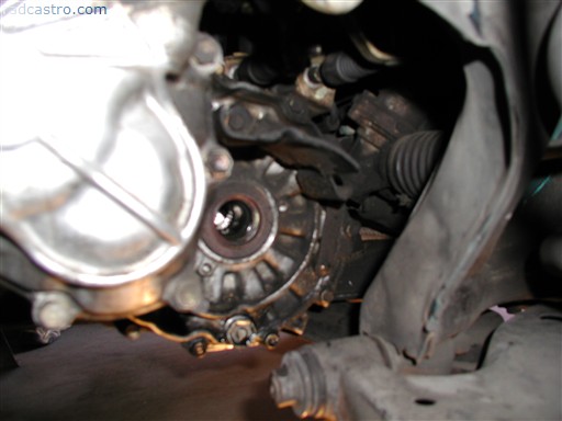
This other thing I'm pointing at is the draining bolt to drain the transmission oil/fluid. The red circle is the driveshaft (halfshaft), it is one of the main things we need to remove. But before we can do any real work we need to drain the tranny (informal name for transmission). Figure 13
So, grab a tray , bucket, or whatever is big enough to get all that oil and unbolt the drain bolt. Figure 14
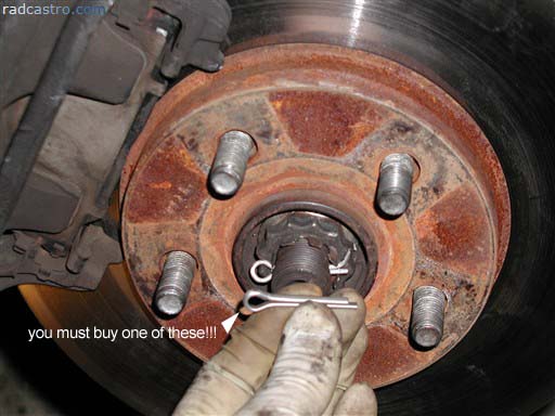
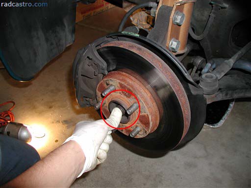
Once the tranny is completely drained, we need to take the wheels off the driver's side. Remove the cotter pin and cap from the rotor and driveshaft. Also, make sure you have a spare set of cotter pins like the ones I'm holding below when we start to put everything back. Figure 15
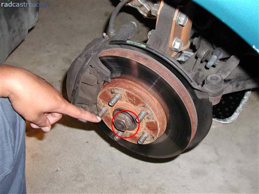
Remove the bolt from the driveshaft as shown below. You will need a large long socket for this. I think it's 24mm I believe. I maybe wrong. Whatever size it is. It should be big. Just make sure you have an arsenal of sockets to tackle the biggest and smallest bolts. Figure 16
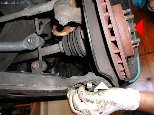
On another note, Be careful to follow assembly specs when putting this part back together. Nothing worse than getting the new axle back in then having wheel bearing noise due to inproper torque on the hub nut! Another hint, measure the depth of the threads sticking out from the nut on the axle before removal and compare after installation. It's possible to obtain proper wheel hub nut torque and the axle spline not be in the hub all the way which would eventually cause wheel bearing failure. (don't ask how I know) If using aftermarket axles the nut thickness may also be different, just pay attention. You'll notice that if you look under the area where the brake rotor resides, you'll see three bolts that lead to separating the suspension from the lower arm control. Figure 17
Once you do that, you need to start trying to push the driveshaft (cv joint) through the rotor hole and at the same time, pull the suspension assembly away from the driveshaft. Figure 18
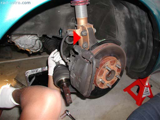
Here is another angle of the removal. (this angle is actually from the passenger side). Nevertheless, the idea is the same. You also get a better angle of the bolts that need to be removed from the lower control arm. Move the suspension assembly in the direction of the white arrow so that it's detached. Then continue to push the shaft in the direction of the red arrow. Use a mallet if you have to. Figure 19
Once you do get the bolts out, move the suspension out of the way (in the direction of the red arrow below) and start tugging and pulling at the driveshaft. You may need to get under the car to pry out the driveshaft. It may take a bit of pulling and to get it out. I ended up using a mallet and a screwdriver on the joint (see red circle on Figure 13 as reference) to get it out from the tranny. Figure 20
When you do finally get the shaft out, you'll see a little hole. This is where the driveshaft will be put back in when everything's done. Figure 21
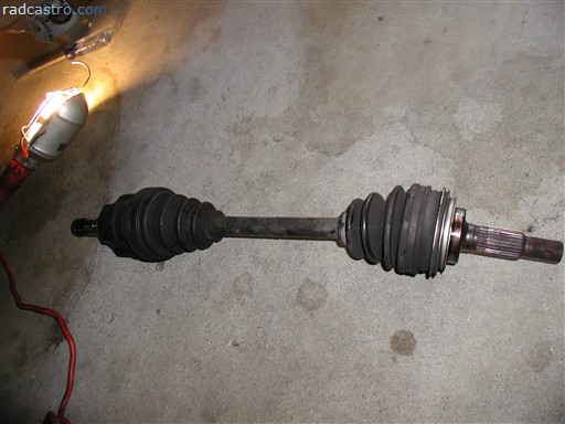
Here's the shaft from the driver's side. Figure 22
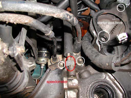
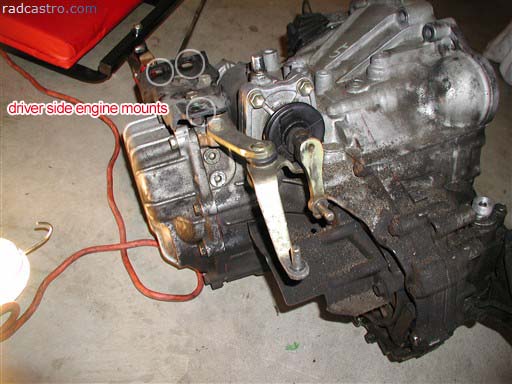
On the passenger side, perform the same steps you did to remove the shaft on the driver's side. When you're done, you should see something similar to figure 23. The circles (from left to right) are the engine mount, the speedometer cable, and the transaxle. This is how it should look like when you get the shaft out from the passenger side. Figure 23
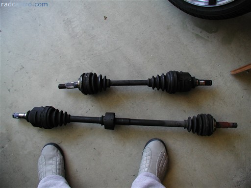
Here are both of the driveshafts. You have now just completed one of the milestones. Figure 24
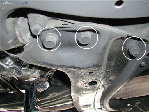
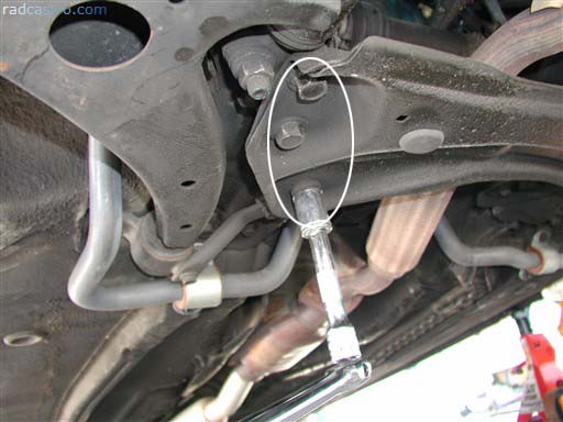
The next thing we need to do is locate the crossmember on the bottom of the car. Note the three bolts. Those are our targets. Figure 25
This is the other side of the crossmember (passenger side). Remove these three bolts as well. Figure 26
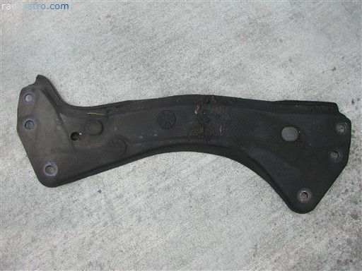
Here's the removed crossmember. Figure 27
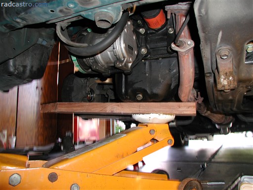
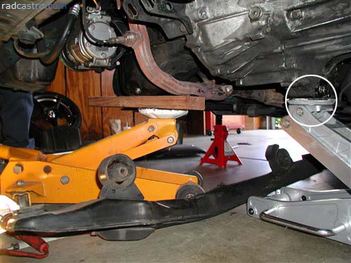
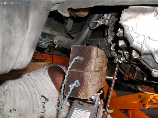
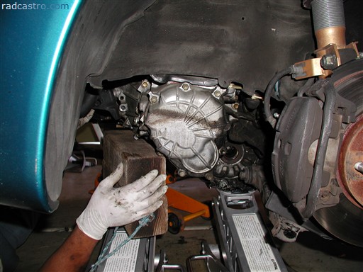
Now here comes the important part. Supporting the engine. If you don't have a an engine hoist with chains then you're going to have to improvise. In my case, I used a piece of wood and a spare hydrolic jack and placed it directly under the oil pan. Figure 28
Again I didn't have the hoist, so I just tied the engine to the strut bar. It's not the best way of course, but I'd rather do that than nothing. Lesson 1: get an engine hoist. If you don't have a strut bar, then you're going to rely solely on the hydrolic jack and wood and pray that the hydrolic jack doesnt give...or else...say goodbye to your engine mount. Basically, all I'm trying to do is not put too much stress on the passenger side engine mount. Figure 29
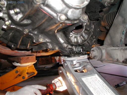
After you've secured the engine, go under the car and look under the area where the crossmember was removed. You'll see the starter. Yes. That grimey thing is my starter. The two circles designate the two bolts that need to be removed on top of the starter. You just can't see them. That's why I circled them Figure 30
Carefully remove the connectors with a flat screw driver and small socket. Figure 31
Here is the starter removed. Note the areas in which the bolts had to be removed. Use this as a reference to get the starter removed if you haven't already. Figure 32
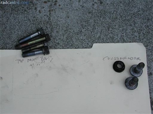
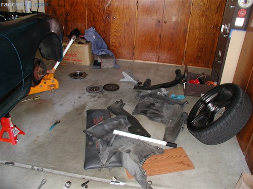
Since you're this far in the install, I hope you remembered to label the bolts and organize the bolts. This article doesn't go that far when it comes to reinstalling everything back. So beware and remember to label your stuff. The better your organize; the better chance you'll have enjoying this experience Figure 33
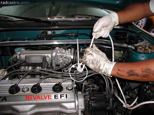
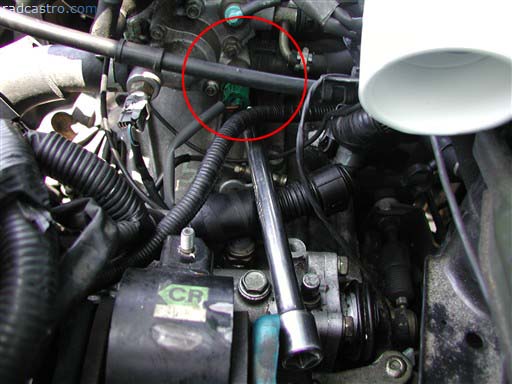
Let's go back to the top of the tranny and remove the remaining stuff (if you haven't already), like the sensor harness and hydrolic line. Figure 34
Here are more of the other things that need to be unbolted from above. Figure 35
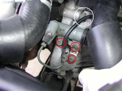
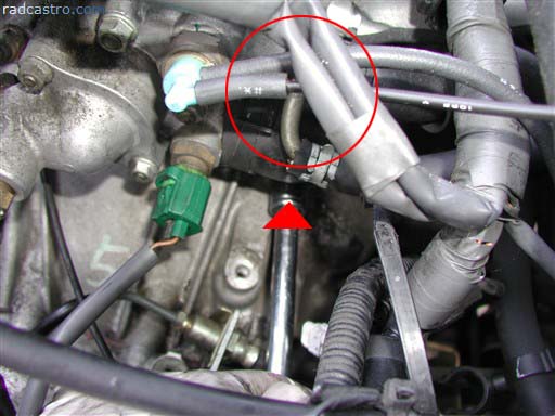
In between the two pipes, you should see the transmission sensor (in the white circle) and the hydrolic line for the clutch throw bearing (in red circles). Remove them all and safely move the hydrolic line line of the way. Figure 36
If you haven't already, go back under the car and remove the bolts that hold down the shift lever lines (unless of course they were already removed). The next thing we need to do is unscrew the speedometer cable. If it's too tight to do it by hand, you may need to use vise grip. Figure 37
Now we begin unbolting the main tranny bolts. Here's one of them. Above the car. Figure 38
Here's another bolt (on top) near the air filter area. Figure 39
And yet another one. This is located near the area where you removed your starter. I know. This isn't a very practical picture. The main idea is to get all the main tranny bolts out. Figure 40
Make sure you examine the pictures carefully to locate the tranny's bolts. We just want to make sure the tranny can completely come off with no problems. Now that we have most of the tranny bolts out of the way from the top of the car, we need to remove any remaining bolts from the bottom. The wheel looking thing on the left is the engine mount. And the other remaining white circle is another tranny bolt. Get the tranny bolt out first... Figure 41
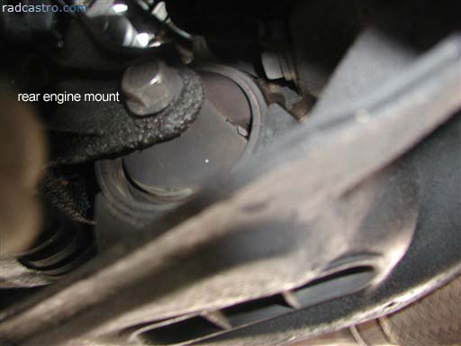
Then while that's going on, you (or your partner) can start unboltingthe rear engine mount (located under the car in the same relative area where you worked on your starter). This bolt doesn't require using a rachet on the other side to hold the nut. The nut is welded. Figure 42
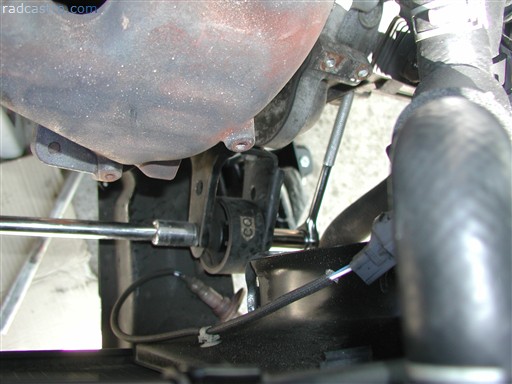
However...the front engine mount does (as shown below). The rear engine mount just needs to work on one side. Figure 43
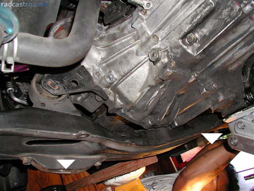
Note on figure 44 the two arrows pointing downward. That is the direction in which we will pull out the center (and remaining crossmember). You'll also notice that the bolt from the front engine mount has been removed. You'll basically want to be at this point before we go on. So yes. Get both the rear and front mounts done before we move further. IMPORTANT: MAKE SURE YOUR ENGINE IS FULLY SUPPORTED. Whether you use a piece of wood, a hoist or anti-gravity pads. Your engine cannot...and I mean cannot...put stress on the passenger side engine mount. You can do what I did, or try something intuitive. Just don't screw up your mount or your engine. Figure 44
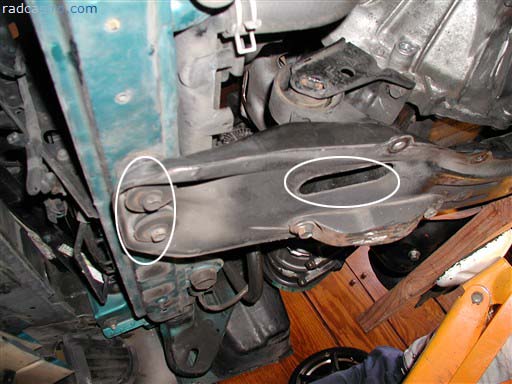
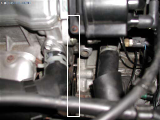
We are now approaching the point of no return. Once we unbolt the remaining bolts as designated below, your engine will be basically floating. Figure 45
Here's another shot of the center crossmember bolts inside the hole. Figure 46
Below are the rear bolts of the center crossmember. You and your partner need to unbolt both the front and the rear at the same time or risk destroying the bolts. Figure 47
Here is the center crossmember. Finally removed. Now the tranny awaits separation. Make sure you have a jack on that transmission. I circled the appropriate placement for you. Figure 48
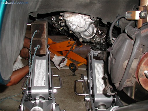
With no transmission jack, we really had to improvise using hydrolic jacks. This is one of them. Figure 49
Here's the other using blocks of wood. These blocks actually came from the back of the cars wheels to keep it stable when jacked. Talk about ghetto. The scary thing is that the transmission is oddly shaped (like most transmissions) and these were the only jacking/holding spots where we can hold it. Make sure the jacks are tightened so that they won't lower by accident!!! Figure 50
Here is a more better angle of how were trying to properly lower the transmission. Now you can see why having a transmission jack would make life easier. Figure 51
Here is a shot of the dropped crossmembers and my friends leg. Figure 52
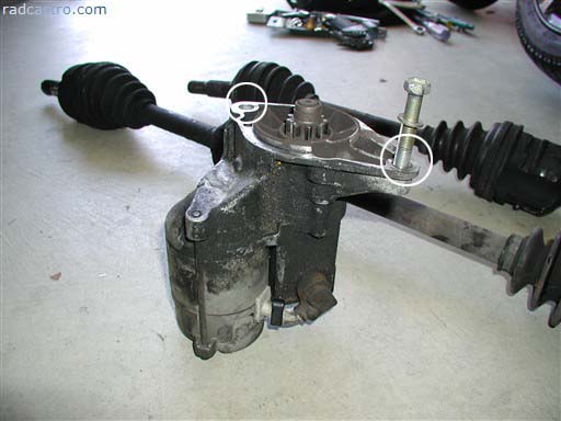
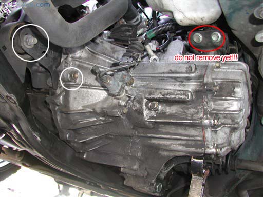
Once the jacks are safely spotted under the tranny, we begin to take out the important bolts. The bolts that free the tranny. Here are two of the three we need to take out. Figure 53
Here is the remaining bolt. If your jacks are properly positioned (or you're using a transmission jack), your tranny should lower itself only a little bit as you're unbolting the remaining bolt. Hopefully, the transmission doesn't fall completely when you do this. That's 200 lbs hitting the concrete! Figure 54
Now with the bolt out, here's where you need to be skilled. Using one hydrolic jack at a time, you will need to slowly lower each one. One by one. Inch by Inch. Alternate between lowering the jacks and be very careful at this point. This is probably one of the most scariest parts of the article. Well. If we had the transmission jack. It wouldn't be this scary. Figure 55
As the transmission starts to separate itself from the flywheel, you or your partner might have to pry it out from the pins as you can see below. Do this carefully. This shot is from the top of the engine. I don't recommend prying from there. Do it from the bottom of the tranny. Figure 56
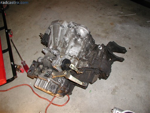
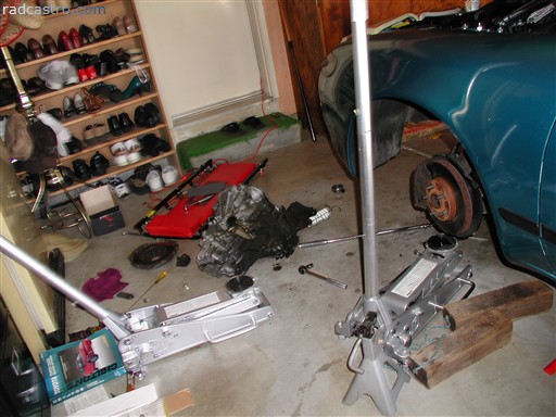
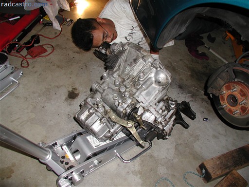
If you're successful in lowering the tranny, you should be able to mimic the picture below at this point. Give yourself a pat in the back. Figure 57
Here is another shot of the tranny. Note the grease and grime accumilated from years on end. Note the area where you removed the shift control. Figure 58
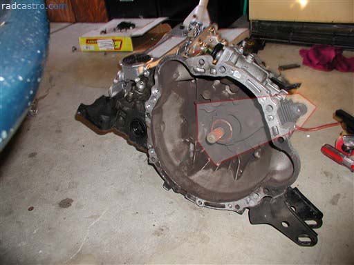
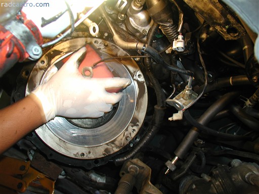
Here is the picture you need to remember. Look closely at how your throw bearing is assembled on the tranny. Take a very close look. I outlined it below. This is important because it is the very thing that engages and disengages your clutch from the flywheel. You will have to remove the throw bearing at this point. Figure 59
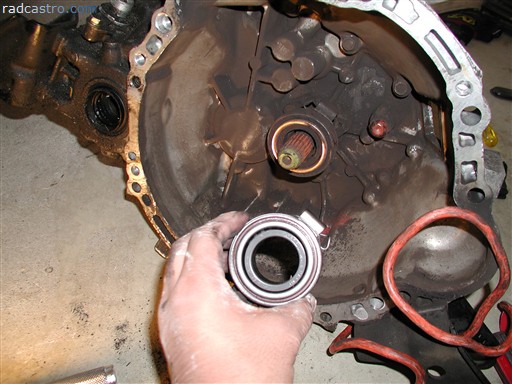
Here is a comparison of the old (behind) vs. the new (I'm obviously holding it). Figure 60
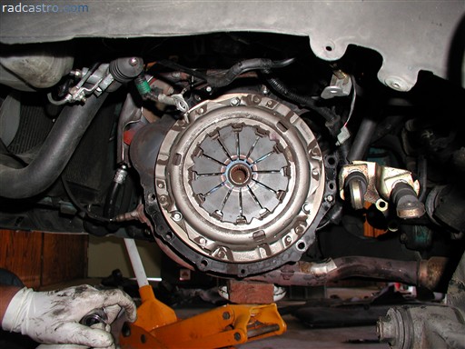
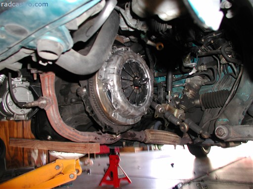
Here's what you've been waiting for. Access to the clutch cover and clutch itself. Figure 61
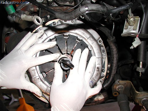
Now you'll need yourself or your friend to hold down the camshaft pulley while the other will remove the bolts from the clutch cover. Holding down the pulley with a ratchet or breaker bar greatly helps out the person trying to unbolt the clutch cover. Figure 62
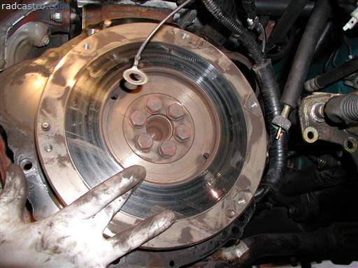
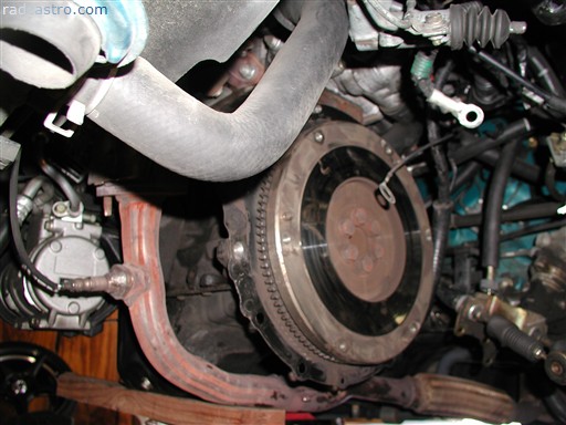
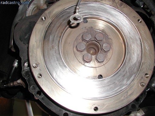
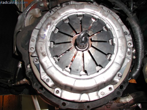
When the clutch cover is finally unbolted, you'll get to see your shiny flywheel. NOTE: flywheels are not supposed to be shiny. If they're shiny, that's a sign of serious clutch slippage. If not, your clutch may still have some life in it. Figure 63
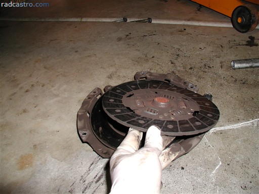
Finally, after the third hour, we have finally removed the clutch cover and what else? Yes. The clutch. <sigh> Figure 64
This is probably the most useless part of the article. Figure 65 shows why. Anyway, I was on the phone trying to find a machine shop to resurface my flywheel. Amazingly, all the shops were mysteriously booked. Stupid lazy machine shops! Anyway, this part of the article is just show n tell. So go and relax for a bit. Figure 65
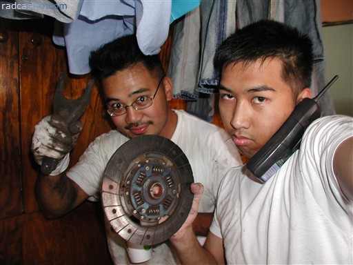
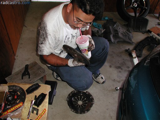
Andy, the old clutch, and jamba juice. Figure 66
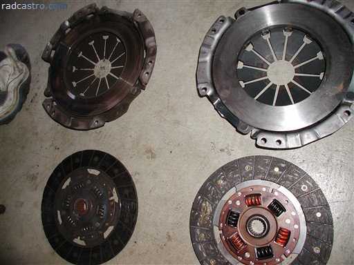
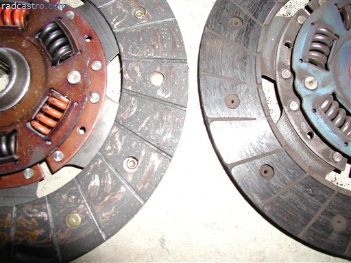
Old vs. new Figure 67
Guess which one's the old clutch. Figure 68
Here's another amazing shot of the flywheel. Figure 69
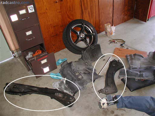
Here's the mess we made. Don't ever leave crap lying around like we did. Organization is a must. Figure 70
Yet...we still seem to make a mess. Figure 71
Since we couldn't find a machine shop to resurface the flywheel. We began to resurface it ourselves with some 250-500 grit metal sandpaper. Make sure you do it in circular motions when "resurfacing". I don't recommend doing this unless you really need your car driven the next day. The day we did this was sunday so I had to get my car back and I had to conduct an important meeting at work the next day. So yeah....slap me for being stupid. Figure 72
If you are reading this, you are lucky. You have survived and we are nearing the final stretch of this clutch install. Anyway, let's continue. With the flywheel specially resurfaced by mr. andy, it looks like this (fig 73). You will need to continue spraying the flywheel with brake cleaner. Make sure you use it liberally. We have to remove any remains of grease as much as possible. The flywheel should be completely clean. Figure 73
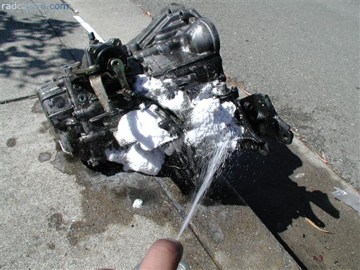
Bust out with the engine cleaner and start cleaning the tranny. Use a hose in addition to the engine cleaner if you want. Just don't do something stupid like stick the hose into the driveshaft holes. Figure 74
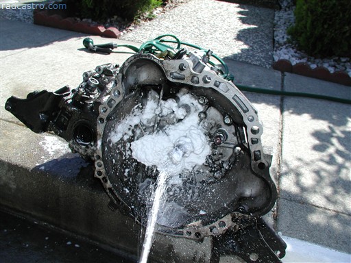
Here is where the cleaning matters the most. Clean this as thoroughly as possible. Wipe everything well within this part of the tranny. It is very important to clean it well. Use the engine cleaner to get most of the grime out and use the brake cleaner last to remove most of the hardest spots. Figure 75
Once you're done cleaning, you putting in the clutch cover and the clutch. Make sure you have the correct side of the clutch facing the flywheel. 99% of the clutches you buy have the sticker "flywheel side" on one side of the clutch. Make sure that side faces the flywheel. I'm seen and heard people do everything right but this. So let this be a friendly reminder. Figure 76
Remember to put the alignment tool on the clutch first before putting both the clutch cover and the clutch itself on the flywheel. Figure 77
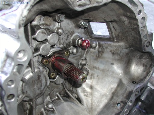
VERY IMPORTANT! The clutch should be perfectly centered before you finally bolt the clutch cover. Why do I emphasize this? Because if the clutch isn't centered well, it will be very hard to get the transmission mounted back on the engine. Basically, as soon as you bolt on the clutch cover the clutch is engaged and the shaft that sticks out of the transmission (as illustrated in Figure 79) will have a hard time trying to find its way back into the clutch hole. In addition, the transmission will not line up with the bolt holes. You will then have to go through the painful process of trial and error. Figure 78
Make sure you use hi-temp grease on these two areas so that the throw bearing can move around easily. The better the grease, the better your clutch petal is going to feel. The red stuff you see below is the high temp grease. Figure 79
Removing the transmission is not as hard as putting it on. So yes...welcome to the hardest part of the install and this whole article. If you have the transmission jack (like I've already recommended many times), your life would be so much easier. This is 200 lbs we're trying to put back. I've heard experiences where it took 2 people to get just the tranny back in two hours. Fortunately for us, we got it on the 1st attempt. Basically, what you want to do is, slam the tranny back and put one (or two) of the tranny bolts on so that your partner or you don't end up bench pressing the tranny. Of course, we used our pair of jacks....but you wouldn't believe how hard this is trying to put the tranny back. So, with the tranny attached back to the engine, everything else was cakewalk. Figure 80
All we had to do from this point was to refill the tranny with gear oil (75 W90). Fill it till it drools. Bolt the fill bolt back on and we're ready to put everything back in the following order:
Figure 81
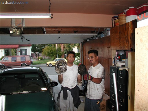
Make sure you test drive the car a couple of times before you can go pose like us below. Congratulations! You've done it. Go now and drive proud. Figure 82
|
|
| ||||