Timing belt changing on 89 Camry with 3s-fe engine The purpose of this masterpiece is to supplement the timing belt changing instructions outlined in the Toyota repair manual in order to help people with limited experience to avoid mistakes. The timing belt change jobs can be divided into the three categories:
Routine change due to recommended mileage or age interval or when the used car is purchased with unknown timing belt change history;
The timing belt needs to be removed in order to change the leaking water pump, oil seal or noisy idler bearing;
The timing belt is broken.
The categories number 1 and 2 [the belt is neither broken nor jumped the teeth and valve timing is NOT lost] are going to be covered in the following work.
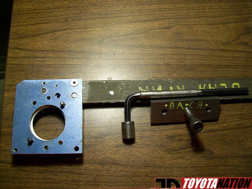
1. Prepare necessary tools: · Breaker bar,1/2 inch drive, with step-down adapter and 19 mm socket · 12 inch long extension 3/8 inch drive · 17 and 14 mm deep sockets 3/8 inch drive · ¼ inch drive ratchet with 10 mm socket · 12/14 mm offset box wrench · 3/8 inch drive short metric sockets, 10 to 22 mm size, 8 and 3 inches long extensions, spark plug socket and reversible ratchet · 10 mm box end offset wrench or 10mm combo wrench; · Torque wrench 20 to 90 foot lbs · Harmonic balancer puller · Crankshaft pulley holding device · Mirror · Paint marker · At least one jack stand and jack · Copy of belt changing procedure from repair manual pages EM23 toEM33].
Note: additional tools can be required.
2. Undo the crankshaft bolt: If the previous service have been done by franchise or tire shop, the crank bolt can be too tight: if electrical impact gun cannot break it loose, the local tire shop may undo the bolt for you, ad then snug it back so you will be able to remove it yourself. Do not attempt to go fast or far after this procedure; go straight back to the belt change.
Turn the front wheel to the right; set the parking brake;
Disconnect negative battery cable
Break loose the lug nuts on the front right wheel,
Raise the car and place it on the jack stand
Remove the wheel and the splash shield to expose the pulley
Lock the pulley with holding device
Break the bolt loose using breaker bar or impact gun.
3. Time for power steering reservoir and right front motor mount:
Unbolt power steering fluid reservoir bracket and move it away without disconnecting hoses; you may wrap plastic bag around it. I also used solid wire to temporary strap the reservoir to the top of the strut tower to keep it out of the way
Place the jack under the engine using care to prevent the oil pan damage
Remove nuts and bolts on the top of motor mount and mounting bracket
Use deep 17 mm socket to remove the most difficult nut facing the firewall; use caution to retrieve it as there almost no space to there [in most difficult case you may need to make some sort of “tool” to catch this nut].
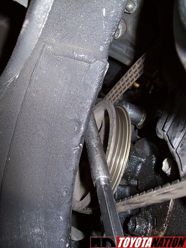
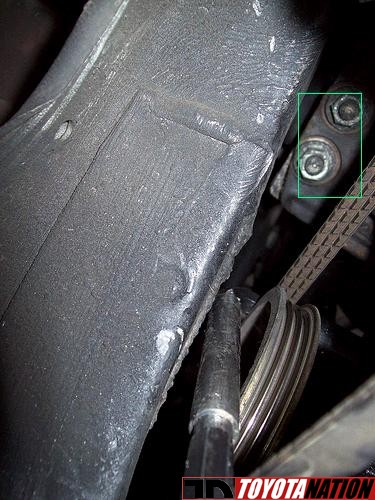
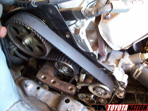
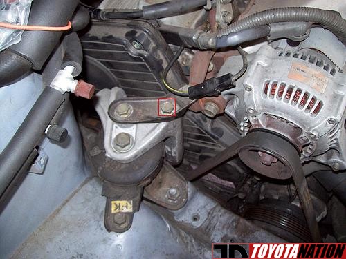
4. Down the fender well: · Slide the special wrench between the frame rail and the power steering pump pulley and place its head on the pivot bolt, figure below: · With the aid of the cheater, break this bolt loose then loosen it about ¾ turn · Using 14 mm offset box wrench, loosen the belt tension bolt, move the power steering pump toward the engine and slip the belt of the pump pulley, let it hang down on the crank pulley; · After verifying that jack under the engine is secure, remove two nuts in the green rectangle; this will separate engine block from mounting bracket. Use 12 inch extension and 14 mm deep socket for this purpose, figure below: 5. Motor mount, timing stetting, and alternator’s time:
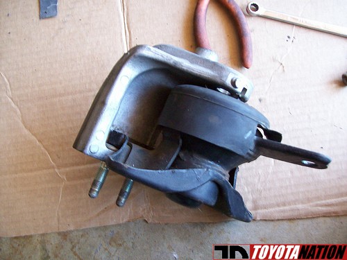
Remove the motor mount and bracket as one piece; it is not possible by design to remove just bracket, then motor mount. Once off the car they can be separated if necessary; figure below
Remove the spark plugs
Pull the 3 inch rubber plug from upper timing belt cover to expose the timing hole on the cam sprocket; place 22 mm socket on the alternator pulley and rotate it clockwise using ratchet
With the aid of mirror align the timing hole in the sprocket with the mark on the cam bearing housing as outlined in the manual.
Now make sure that the timing mark on the crank pulley lines up with “0” on the timing scale
Disconnect and remove alternator and its bracket
Remove drive belts from the crank pulley
Completely remove crank pulley bolt
Using harmonic balancer puller or bar type puller take the pulley off [use M6 class10.8 or stronger screws to attach puller to the pulley]
Using 10 mm socket and ¼ inch drive ratchet, remove the timing cover screws and timing covers; the upper cover may come out easier if the power steering return pipe is pushed toward the strut tower. Moving engine up or down with the jack may also help to maneuver the upper cover out
Remove the timing belt guide
6. The fun with the belt: The “pretension” of the belt is done by a tension roller spring during the manual rotation of the engine right after the belt installation; once the roller’s bolt is tightened, spring has no effect on the belt tension. In order to assure correct timing phase there should be certain number of belt teeth between two timed pulleys [cam and crank]
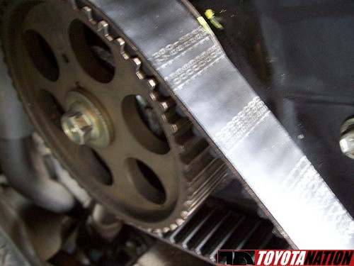
Using quick drying marking pen, place the marks on the cam sprocket and #3 timing cover; this will make the cam position easy to see, figure below
Match mark the belt to the cam sprocket as illustrated, figure below
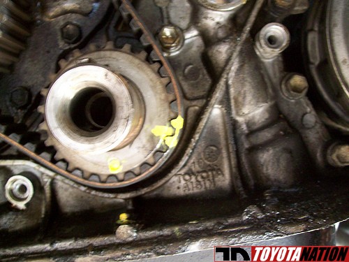
Match mark the belt relative to the crank sprocket, figure below
Mark the side of the belt which is facing the radiator
Loosen the belt tension roller bolt
Use appropriate tool to push the roller down to free up the belt, then temporary tighten the roller bolt
Slide the belt out
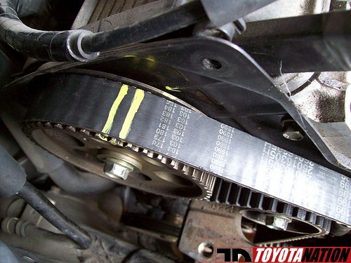
Place random mark on the new belt [two teeth next to each other]
Line up old and new belts side by side on the flat level surface and align the marks
Transfer remaining mark from old to the new belt
This will assure same number of teeth between the marks on old and new belt which is critical to set the timing phase.
Inspect rollers, seals, bearings and do necessary repairs
Install the new belt, make sure that each of the marked teeth on the sprockets is placed between 2 marked teeth on the belt, figure below
Loosen the bolt to allow the tension roller to contact the belt under spring force
Install the belt guide, lower timing cover and crankshaft pulley, snag the pulley bolt in
Rotate engine 2 full turns clockwise and recheck the timing marks
Rotate the engine clockwise 1 and 7/8 turns and tighten the tension roller bolt to about 35 foot-pounds
Install the upper timing cover and the rubber plug
7. Proceed to assembly:
Place the motor mount and bracket on its position then insert the long bolt in red square into its hole and begin to thread it in. This will bring the mounting bracket and the engine block into the proper alignment in order to install and tighten 2 engine to mounting bracket nuts, figure below
Once nuts are tightened remove the long bolt, place mounting bracket to alternator bracket brace and install all bolts and nuts to secure bracket to the mount and mount to the body. Reinstall and tighten the long “alignment“ bolt
Install spark plugs, alternator and drive belts
Remove jack from under the engine
Position holding device on the crank pulley
Place torque wrench on the crank pulley bolt, torque to 80 foot pounds
Install splash guard and wheel
Lower the car, torque the lug nuts to 80 foot-pounds
Install the power steering reservoir
Reconnect the battery
You should be ready to go.
Submitted by xxx@******.com
Revision 0
Article submitted on 30 Mar 2010
Last modified on 5 Apr 2010 Viewed 19808 times
Please enable / Bitte aktiviere JavaScript! Veuillez activer / Por favor activa el Javascript![ ? ]