|
Disclaimer: By using this “Front Wheel Bearing Replacement” walkthrough you are agreeing to hold the author of this article harmless of everything, including injury and/or damage to your vehicle, tools, residence/garage, yourself, friend, etc. It is recommended that a mechanically knowledgeable person or qualified mechanic attempt this project only. No warranty is expressed or implied. Always work on your car with proper tools and safety equipment. USE THIS ARTICLE AT YOUR OWN RISK, THE AUTHOR IS NOT LIABLE FOR ANY PROBLEMS OR INJURY THAT MAY ARISE. Front Wheel Bearing Replacement By hyoctane Car: 2001 Toyota Celica GT-S (ZZT231), 6-Speed (C60), w/o ABS. Mileage: 84,XXX miles Parts Required: 30mm 12 point locking axle nut, radial ball bearing (front passenger/drivers side) and a cotter pin (again, one per side.) These parts can be purchased at your local Toyota dealership parts department for under $40.00. Minimum Tools Required: Jack, jack stands, wheel chocks, breaker bar, Pittman arm puller set, ratchets, torque wrench, 30mm or 1 3/16” 12 point deep socket, 19mm socket, 17mm socket, 14mm socket, 10mm socket, hammer, two 8mm bolts (purchase pairs of 8mm in all pitches), punch set, large flat head screwdriver, needle nose pliers, zip ties, Mechanix gloves, safety glasses and a friend. Optional Tools: PT Blaster (to help break loose old stubborn bolts), Butane torch (to soften the locking axle nut), Lithium grease (to help slide the axle through the spindle) and a light thread locker (to hold those parts back together.) Now that everything is out of the way, welcome to my front wheel bearing replacement walkthrough, performed on my 2001 ZZT231 w/o ABS with a C60 manual transmission. It is important that you note whether your car has ABS or not, as this walkthrough is ONLY for a Celica w/o ABS. This task will take anywhere from 1.5 to 3 hours to remove your steering knuckle and wheel spindle, which need to be taken to a machine shop for bearing removal and to have the new bearing / spindle / knuckle hydraulically pressed back together. I had my new bearing pressed at a local machine shop for $45 the same day. Overall I would rate this task as a 3 out of a 5 star rating system in difficulty. Be sure you have the proper tools before you attempt this task or you will be without a car until you find the required tools. Now, on with the walkthrough... Step 1. Pull your emergency brake, jack up your car, place it on jack stands, place wheel chocks at the rear wheels and remove your two front wheels. 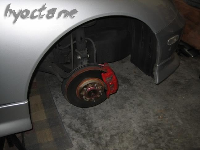 Note: This is the simple step. If you don’t know how to perform this step, please stop working on your car and take it to a knowledgeable / qualified mechanic or your local Toyota Dealership. Also, make sure your brakes and engine are cool to the touch to keep from burning yourself. Step 2. Locate the notch on the end of the axle and notice that the locking nut has been indented in this notch to lock it on the axle. Grab your punch or strong screwdriver and begin to hammer the indentation out of the nut so you can remove it.  Note: This is the most frustrating part of the project. Plan on spending 15 minutes or more doing this. I used a combination of butane torch to soften the indentation in the nut and a punch to hammer it out. Be sure not to damage your axle or threads on your axle. Step 3a. Get your friend in your car, start it and hold the break pedal down. Turn the steering wheel so you can access the locking nut without damaging your wheel well. Use your 30mm or 1 3/16” 12 point deep well socket and a breaker bar and begin to loosen the nut. Note: I used some PT Blaster to help break it loose as it was extremely stubborn. With a little persuasion, this task won’t take too long. Just be sure that the indentation on the nut is completely hammered out of the notch in the axle. Step 3b. If installed, remove your hub centric rings. I have lightweight aluminum rings from my Rays wheels, some cars may have these installed some may not. I used a thin flat head screwdriver and a hammer to remove them. Step 4. Remove the two 14mm bolts that hold the caliper on. This is just like changing your brake pads. Remove your caliper and suspend it from your spring with strong zip ties. This will ensure that you don’t damage your brake lines. Next, remove your brake pads, and the caliper bracket which is held on by two 17mm bolts. 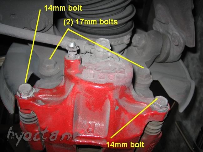 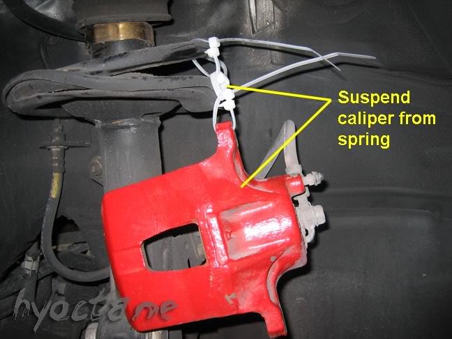 Step 5. Use your two 8mm bolts and locate the two bolt holes in your rotors near the wheel studs. Spray some PT blaster in the holes and begin to thread in the bolts. Keep turning them and eventually the rotor will pop off of the spindle. Be sure you have the right pitch on the 8mm bolt. I don’t remember the exact pitch, so verify w/ the bolts that you bought. Return the unused bolts. 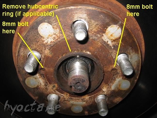 Step 6. With the rotor off, locate the two 19mm nut and bolt that hold the steering knuckle on to the shock absorber. Loosen both nut and bolt combination. Do not completely remove them as this will help with the next two steps. Note: The nut is on the back side of the shock absorber (facing the firewall.) You should place your socket here and loosen, and not the bolt side toward the front of the car. 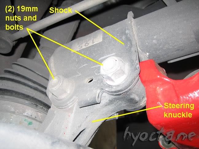 Step 7. Locate your tie rod, which is located toward the firewall of your wheel well. Remove the cotter pin and take your 17mm socket and remove the nut from the stud. With the nut removed, use your Pittman arm puller and place over the stud. Make sure it securely grabs the steering knuckle and not the ball joint end of the tie rod. Give it a few twists with your ratchet and the tie rod will literally “pop” loose. Remove the Pittman arm puller and place the tie rod aside. Note: This is a simple step with the right tools. I was loaned this “Puller” set from a local Autozone for free, all that was required was a 100% refundable $89.00 deposit on the tools. 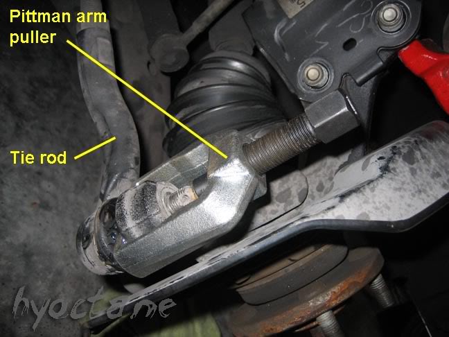 Step 8a.Next, locate the two nuts and one bolt that hold the lower ball joint of the steering knuckle to the lower control arm and remove them with a 17mm socket and breaker bar. Remove the two nuts before you remove the final bolt. Note: I used some PB Blaster on the nuts and bolt here. This was another extremely difficult task, as they are torqued with over 100 ft/lbs. Be sure to use your breaker bar and to hold the socket over the bolt with your hand, or you may end up stripping the head of the bolt due to the angle of the control arm. Also, break all of the nuts and bolts lose before completely removing them. Remove the two nuts first, and then the bolt. 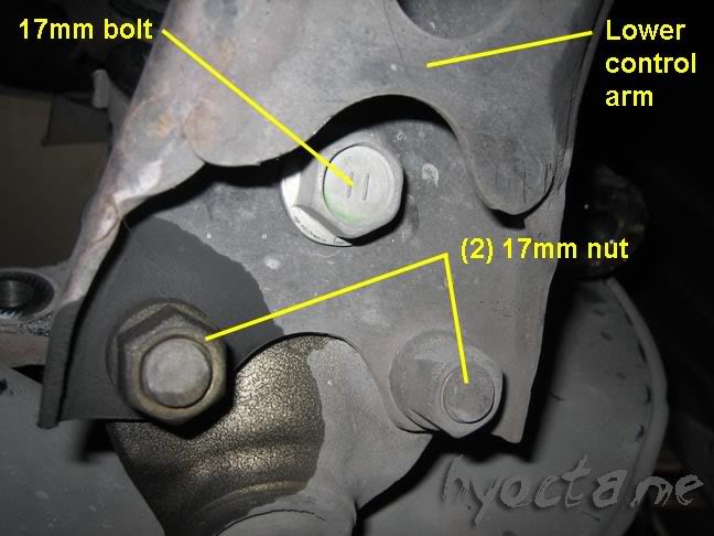 Step 8b. Remove the two nuts and bolts that hold the steering knuckle to the shock absorber. They should all ready be loosened from step 6. Note: Be sure to place a shop rag or similar between the top of the constant velocity (CV) boot and the bottom of the shock absorber. This will keep the lower control arm from pushing the CV boot up into the shock, puncturing the boot. I cannot stress this enough, just do it. Step 9a. With all bolts holding the steering knuckle on removed, grab the top of the knuckle with your hand (where it was attached to the shock) and hold it firmly. Grab a hammer and begin to tap the axle out from the spindle. Note: Do not pull the knuckle / spindle away from the axle, as you may damage your axle or drive train. Also be sure you don’t damage the threads on the axle when striking it with a hammer. This will take many repetitious light blows, and may take a while. Be patient as you don’t want to hit a wheel stud or bend the threads. Step 9b. With the steering knuckle / spindle assembly removed, inspect the CV boot for any wear or damage. Now is the time for this as you can readily examine the boot without hindrance. Replace as necessary (this walkthrough does not cover CV joint or CV boot replacement. Please consult a qualified mechanic for this job.) 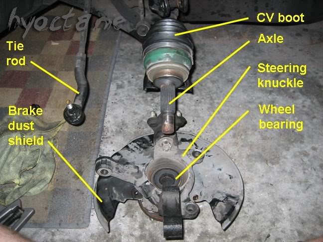 Step 10. Remove the dust shield. There are three 10mm nuts that need to be removed. Take note that the dust shield will freely spin around the spindle with the bolts removed and will only completely be out of the picture when the spindle is removed. Step 11. With the steering knuckle / assembly removed, securely place in a vice. Grab your old locking nut and socket, and place over the INSIDE of the wheel bearing. Make sure you place it exactly center in the bearing as you are going to press the outer race and spindle out. Attach your tie rod end puller to the knuckle and begin to tighten the socket / nut into the bearing. After a few turns the spindle with separate from the bearing with the outer race attached. The dust shield will now be able to be removed from the assembly. Using needle nose pliers, remove the snap ring holding the bearing in place. 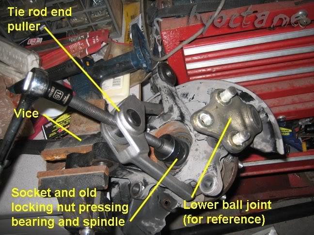 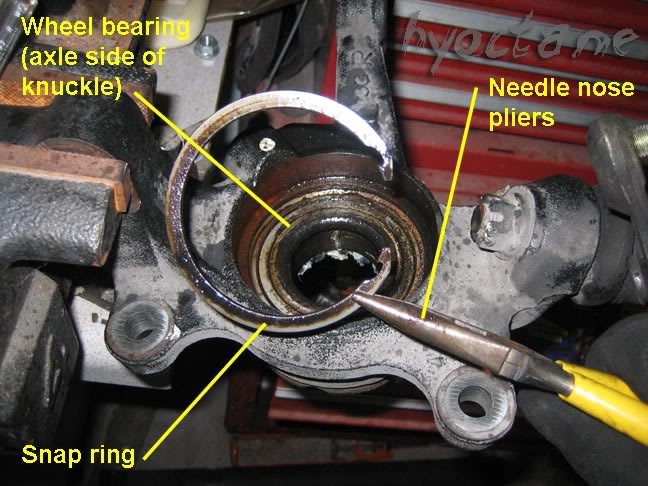 This is the final step of the walkthrough. You must now take your spindle with the outer race of the bearing and your steering knuckle w/ the remainder of the bearing to a qualified machine shop to have the race removed from the spindle and the old bearing pressed from the knuckle. They also need to press in the new bearing and spindle with the dust shield in place. This was only $45 at a local machine shop and $100 at Toyota, however, your price may vary. Reassembly will be in reverse order. I used some Lithium grease to the axle before I slid it back into the spindle, and also used thread locker (per instructions) on all nut / bolt connections (besides the locking nut on the axle and brake bolts) when reassembling. Be sure to torque everything down according to the Toyota Repair Manual specifications. Also, when installing the locking nut on the axle be sure to “punch” the nut at the tab in the axle for a secure connection. Take it for a SLOW test drive and make sure everything is assembled correctly. Check the torque on ALL nuts and bolts after a few days worth of driving. Submitted by xxx@******.com Revision 0 Article submitted on 30 Mar 2010 Viewed 13498 times |
|
|
||||